Anel, Escriptions – dbx 1231 Equalizer User Manual
Page 8
power switch or a master equipment power switch. Since the 12 Series Equalizers consume a relatively small
amount of power, the units may be left on continuously.
r
ear
p
anel
d
esCrIptIons
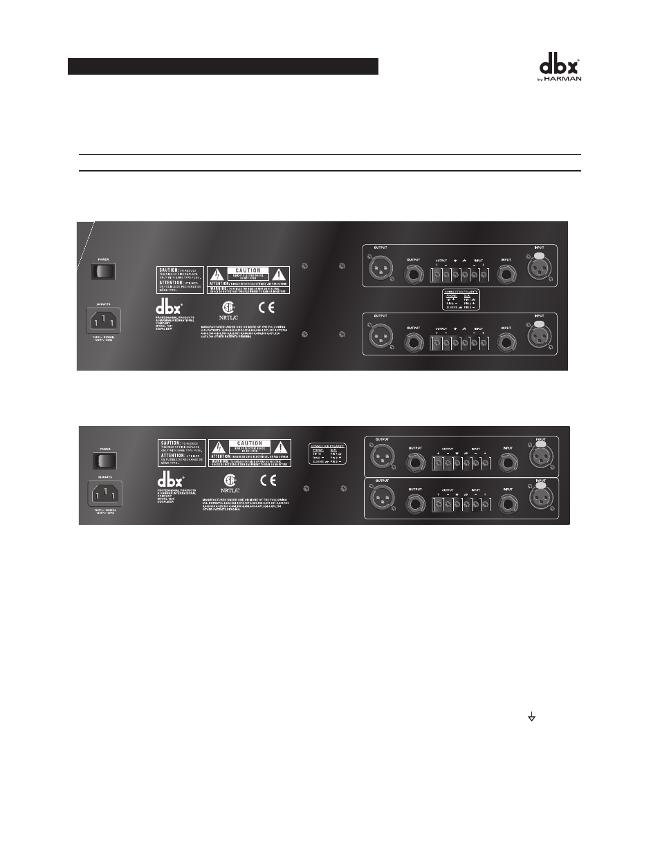
Rear Panels
1231 - dual channel 31 band graphic equalizer
1215 - dual channel 15 band graphic equalizer
Power Switch: Switches the power on and off. Always make audio connections with the power switch in the OFF
position.
Power Cord Receptacle: Connects AC power to the equalizer.
Output Connectors: Three types of output connectors are provided for output connections: male XLR type con-
nectors, 1/4" tip-ring-sleeve phone jack connectors and a barrier strip.
Input Connectors: Three types of input connectors are provided for input connections: female locking XLR type
connectors, 1/4" tip-ring-sleeve phone jack connectors, and a barrier strip. The maximum input level that the equal-
izer can accept is +22dBu (ref: 0.775Vrms).
Chassis ground Lift Strap: By removing the jumper connecting the two screws on the barrier strip, the chassis
ground is separated from the circuit ground of the equalizer. This is sometimes necessary to prevent “ground loops”
in a sound system. When lifting the ground strap, you must make a connection from the circuit ground (
+
+
+
+
+
+
+
+
Without Jumper in Place
With Jumper in Place
jumper
optional
circuit
ground
chassis
ground
circuit
ground
chassis
ground
to system
ground
optional
WIRING CONNECTIONS WITH GROUND
Input
Cable
Output
Cable
Input
Cable
Output
Cable
) terminal
to some other ground point in your audio system in order for the equalizer to function properly.
4
OPERATION MANUAL