Panel descriptions, Front panel – dbx TR1616 User Manual
Page 10
TR1616
Owner’s Manual
4
panel deScriptionS
Front Panel
1
7
8
9
10
2
3
4
5
6
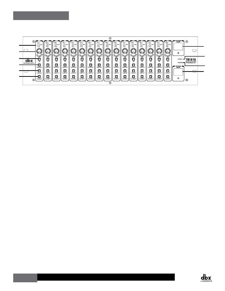
1� 4-Segment Input Meter
These meters display the input signal level for each channel.
2� GAIN knob
These knobs adjust the input gain for each channel. The range of these controls is 0 dB
to +60 dB (XLR input) and -15 dB to +45 dB (1/4” input).
3� +48 Button
+48 Volts of phantom power is available for condenser microphones and direct boxes
which require it. These buttons enable and disable the phantom power for each channel.
The button’s LED will light when the function is engaged.
4� 20dB PAD Button
These buttons enable the 20dB pad for each channel, which can be used to prevent the
preamp input from being overdriven. The button’s LED will light when the function is
engaged.
5� LOW CUT Button
These buttons enable and disable the low cut filter for each channel. This filter is a low
cut filter with a cutoff frequency of 80 Hz. The button’s LED will light when the function
is engaged.
6� POLARITY Button
These buttons enable and disable the 180
0 polarity inversion for each channel. The
button’s LED will light when the function is engaged.
7� TRANSMIT BANk Display
This dual 7-segment display shows which bank on the BLU link network the TR1616
is transmitting its audio on. Each bank consists of 16 channels. Each TR1616 on the
network must have a unique TRANSMIT BANK selected. The desired TRANSMIT BANK
can be selected by adjusting the slotted control below the display. See “Making
Connections–Cabling” > “BLU link” for further information on this display.