Ssi.doc, rev. a, ip rev. b/c/d, rp rev. e, vp 4 – Ironwood Electronics SS-BGA User Manual User Manual
Page 5
SSI.doc, Rev. A, IP
Rev. B/C/D, RP
Rev. E, VP
4
Tel: (800) 404-0204 • (952) 229-8200
Fax: (952) 229-8201
11351 Rupp Dr. Suite 400, Burnsville, MN 55337
www.ironwoodelectronics.com
Socket Assembly
Refer to figure 4 for graphical illustrations.
1. Install the socket base assembly onto the target PCB with the hardware (socket base screws)
provided. Because of asymmetrical tooling holes, the socket can be assembled with only one
orientation.
2. Open the clamshell lid and place BGA package (solder ball side down) into the socket. NOTE:
BGA orientation on target PCB is critical. If an IC frame (optional) is supplied, place it over the BGA
package. This IC frame may be necessary for packages which the encapsulate around the die does not
extend to the edge of the IC’s substrate.
3. Close the clamshell lid.
4. Turn the compression screw clockwise, until the compression plate makes contact with the BGA
package.
5. Turn the compression screw further so that BGA balls are compressed on the spring pins to make
contact. When turning becomes hard, full compression is achieved. Internal stops will prevent over
compression when turned by hand.
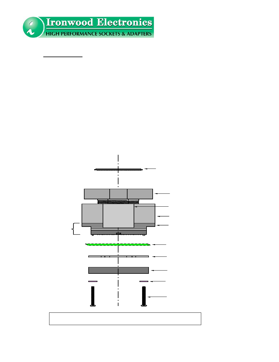
Figure 4: Graphical Illustration of Socket Assembly
S o c k e t l i d
C o m p r e s s i o n S c r e w
S o c k e t b a s e s c r e w
C u s t o m e r ' s P C B
N y l o n w a s h e r
C u s t o m e r ' s B G A P a c k a g e
S o c k e t B a s e
A s s e m b l y
I n s u l a t i o n p l a t e
B a c k i n g p l a t e
L a t c h
S o c k e t B a s e