Ironwood Electronics Bottom Termination Soldering Techniques User Manual
Ironwood Electronics Hardware
Page 1 of 2
Bottom Termination Soldering Techniques
Tel: (800) 404-0204
www.ironwoodelectronics.com
The Ironwood Electronics, Bottom Termination adapters are designed to solder to the
standard gull-wing type quad flat pack
(QFP) surface
mount land pattern. Because Ironwood
Bottom Terminations adapters do not
emulate the physical characteristics of a QFP
gull-wing package, the methods used to
solder it to a target PCB are different. The
recommended method is explained below
with visual aids showing the step-by-step
process. This method has produced very
good results.
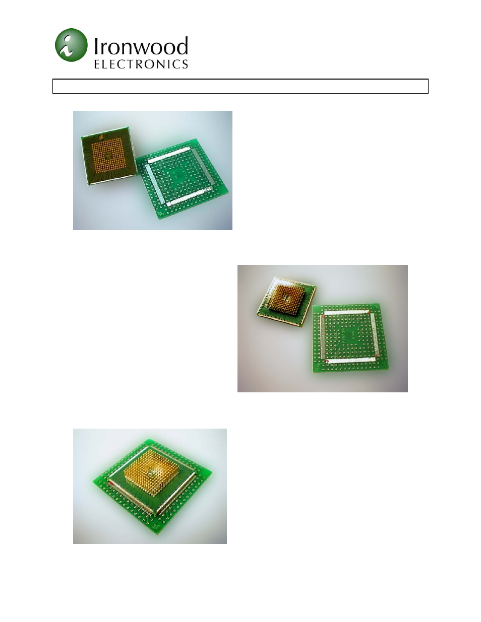
Figure 1 shows a Bottom Termination
surface mount emulator foot and a clean target printed circuit board. The bottom side of
the surface mount foot is
covered by 0.005" thick kapton tape to
provide insulation and clearance from the
target PCB as recommended by IPC-A-
610B, Section 10.2.1 chip
components/bottom only termination
standard.
The steps involved in the soldering
process are as follows:
(1) Using a flux dispenser, place a small
amount of Tac flux (water soluble or no
clean) on the four corner pads of the
target PCB as shown in Figure 2.
(2) Note the target board QFP land pattern and
the adapter Pin 1 locations. Place
the adapter onto the flux and land pattern as
shown in Figure 3. Handle the adapter by
grasping the PCB edge (handle by pins when
available) and aligning it on the land pattern
with the aid of a microscope.
(3) Holding the adapter in place, by pressing
down gently, use the soldering iron and tack
the four corner pads with the aid of a
microscope. This will keep the foot in
alignment.
Figure 1: Target PCB/Emulator Foot
Figure 2: Placing Tac Flux
Figure 3: Align the Foot to PCB