Ironwood Electronics Probe Board With GHZ BGA Socket Assembly Instructions User Manual
Probe board with gh, Bga socket, Assembly instructions
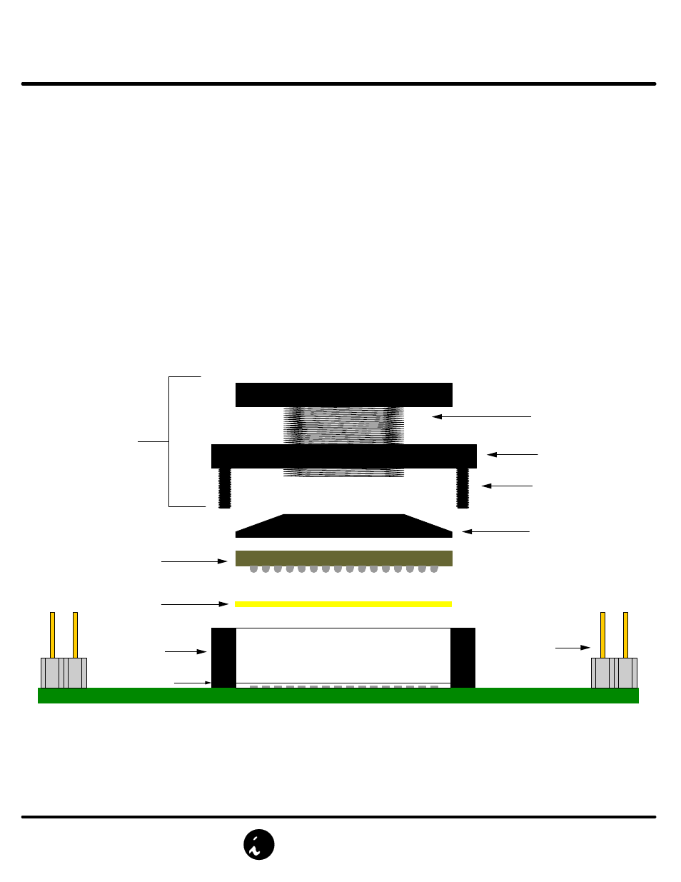
Socket Base
Filename: GPI.mcd, Rev A, 1/18/00, IP
Socket
Top Assembly
Compression Screw
Compression plate
BGA Package
Z-Axis Elastomer
Machine Screw
Socket Lid
Ironwood Electronics Probe Board with GHz BGA socket
Probe board
Test Points
Alignment plate
Probe Board with GH
Z
BGA Socket
Assembly Instructions
© 2000 IRONWOOD ELECTRONICS, INC.
Tele: (800) 404-0204
www.ironwoodelectronics.com
1. Place the square piece of elastomer provided into the socket base (rotational and 'side up' orientation are not critical).
2. Adjust the elastomer to sit into the alignment plate cavity.
3. Place BGA package (solder ball side down) into the socket. NOTE: BGA orientation on target PCB is critical.
4. Place the compession plate (if required*) on top of the BGA package.
5. Install the socket top assembly with the hardware provided (four 0-80 screws).
6. Turn the compression screw clockwise, until it makes contact with the compression plate or the BGA package.
7. Turn an additional quarter-turn.
*Ironwood Electronics technical staff will determine (from your package spec) if a compression or alignment plate is required