Diagram #5, Diagram #7, Diagram #6 – Derale Performance Direct Fit Jeep Wrangler Remote Transmission Cooler Kit User Manual
Page 3
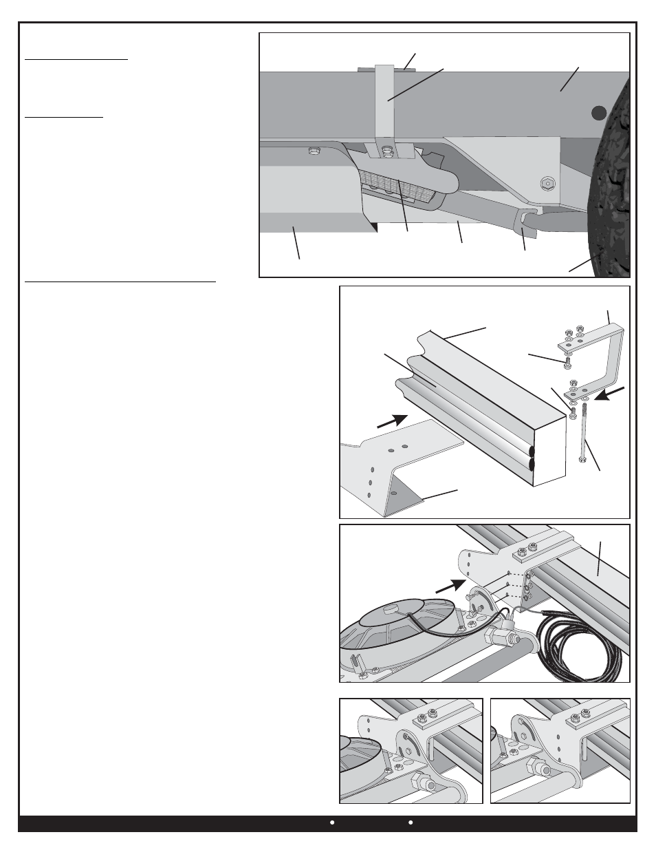
Frame Rail
Bolts, Washers,
Star Washers & Nuts
Outer Frame C Bracket
Frame Rail
Drivetrain
Cooler
Assembly
Inner Frame J Bracket
Exhaust
Skid Plate
Rear Tire
VEHICLE INSTALLATION
COOLER LOCATION
VEHICLE PREP
The Cooler Assembly mounts on the drivers
side frame between the rear trailing arm and the
transmission/transfer case skid plate. See
Diagram #5
1.
Park vehicle on a solid, level surface and
allow vehicle to completely cool before
beginning installation.
2.
Disconnect Positive lead on the vehicles
battery.
3.
With the transmission in park, engage the
emergency brake. Carefully raise the
vehicle using the appropriate floor
jack/lifting device.
4.
Properly place four jack stands, one for
each corner of the vehicle. Refer to the
vehicles owners manual for the proper
lifting locations.
Diagram #5
MOUNTING THE COOLER ASSEMBLY
1.
Identify the Inner Frame J Bracket and the
Outer Frame C Bracket.
2.
Identify the following hardware, (1) 5/16-18 x 5” Bolt, (1) 5/16-
18 x 1 1/4” Bolt, (1) 5/16-18 x 1” Bolt, (6) 5/16 SAE Flat
Washers, (3) 5/16-18 Lock Nuts
3.
Take the Inner Frame J Bracket. The longer leg sets on the top
of the vehicles frame allowing the shorter leg to butt up against
the side of the frame just below the vehicles fuel/brake lines.
See Diagram #6
4.
Take the Outer Frame C Bracket. This bracket slides from the
outside of the vehicles frame over the top of the Inner Frame
Bracket and around the vehicles frame. See Diagram #6
5.
Using a 5/16” SAE Flat Washer, take the 5” bolt and install it
into the bottom hole closest to the vehicles frame sliding it all
the way up through the inside upper hole. Install a 5/16” SAE
Flat washer and 5/16-18 Lock nut on the top of the bracket
assembly and hand tighten. See Diagram #6
6.
Using the 5/16-18 x 1” Bolt, SAE Washers, and 5/16-18 Lock
Nut, install this bolt in the upper outside hole and hand tighten.
7.
Using the 5/16-18 x 1 1/4” Bolt, SAE Washers and 5/16-18
Lock Nut install this bolt in the bottom outside remaining hole
and hand tighten. See Diagram #6
The frame brackets can be moved forward or back
along the frame to assure clearance of the Cooler Assembly.
8.
Identify the following hardware, (3) 1/4-20 x 3/4” Bolts, (3) 1/4”
SAE Flat Washers, (3) 1/4” Star Washers, (3) 1/4-20 Lock Nuts
9.
Take the Cooler Assembly and hold it up to the Inner Frame
Bracket Assembly and Install 1/4-20 Bolts, Flat Washers, Star
Washers and Lock Nuts as shown in Diagram #7
Cooler Assembly has a built in pivot mounting
system. This will allow you to pivot the cooler to not only clear
all vehicles obstructions but to allow you to improve airflow on
vehicles with extra body clearance. Always adjust Cooler
Assembly with the maximum angle without touching any of the
vehicles components.
10. Once Cooler Assembly is in the desired location, be sure to go
back and tighten all mounting hardware.
Outer Frame C Bracket is designed to bend up against
the Inner Frame J Bracket causing a clamping effect.
NOTE:
IMPORTANT:
NOTE:
Derale Performance, Los Angeles, CA
800.421.6288 www.derale.com
(Page 3)
Diagram #7
Frame Rail
Inner Frame
J Bracket
Outer Frame
C Bracket
5/16-18 x 1”
5/16-18
x 1-1/4”
5/16-18 x 5”
Factory Fuel/
Brake Lines
Diagram #6
Forward Mounting
Back Mounting