4 slowdown speed, 5 speed2 and speed3 – R&M Materials Handling VARIABLE SPEED CONTROLS CMXC 022 Service Manual User Manual
Page 12
R&M Materials Handling, Inc.
4501 Gateway Boulevard
Springfield, Ohio 45502
P.: (937) 328-5100
FAX: (937) 325-5319
12/14
R&M Materials Handling, Inc. reserves the right to alter or amend the above information without notice.
MS2
EP2
EP3
MS4
DI2
S2
S2
S2
S2
DI3
HSP
AP
HOLD
SP2
DI4
S12
S11
AP
SP3
DI5
S22
S21
S11/S21
HSP
Description of the control signals:
S1
Drive command forward
AP
Acceleration command
S11
Slowdown limit forward
S12
Stop-limit forward
SP2
Speed2
HSP
High speed
S2
Drive command reverse
HOLD
Hold speed command
S21
Slowdown limit reverse
S22
Stop-limit reverse
SP3
Speed3
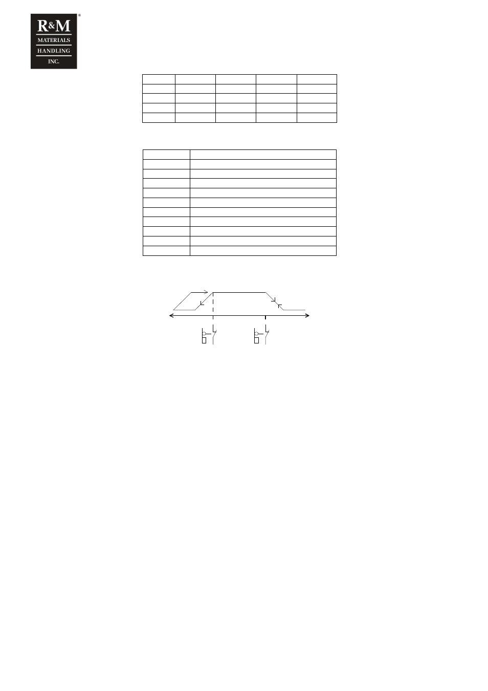
3.4 Slowdown speed
S1
S21
S11
EP2
EP3
S2
Slowdown frequency is activated in EP2 and EP3 control modes when the slowdown limit circuit is opened. In EP2 there
are separate inputs for both limit switch, therefore it is possible to drive high speed in the slowdown area in the safe
direction. In EP3 there is only one input and therefore the speed is limited in both directions in the slowdown area. There
are two alternatives for the level of slowdown speed which are selected by switch S6-3 as follows:
S6-3 = 0
Slowdown speed is 20% of the maximum speed (set by switch S1)
S6-3 = 1
Slowdown speed is 35% of the maximum speed (set by switch S1)
3.5 Speed2 and Speed3
In MS4-control mode the lowest speed level is set by switch S2 and the highest level by switch S1. There are two
alternative settings for the speed2 and speed3, which are set as a percentage of the maximum speed by switch S6-3 as
follows:
S6-3 = 0
Speed2 is 20% of maximum speed and speed3 is 40% of maximum
S6-3 = 1
Speed2 is 30% of maximum speed and speed3 is 50% of maximum