2 exceptional situations, 3 warning and fault codes, 1 determining movement direction – R&M Materials Handling VARIABLE SPEED CONTROLS ControlMaster NXT Service Manual User Manual
Page 47
R&M Materials Handling, Inc.
4501 Gateway Boulevard
Springfield, Ohio 45502
P.: (937) 328-5100
FAX: (937) 325-5319
47/53
R&M Materials Handling, Inc. reserves the right to alter or amend the above information without notice.
9.2
Exceptional situations
9.2.1 Determining movement direction
The frequency converter needs to know in which direction the motor is running to execute the limit functions
properly, because it has only one input for the slowdown limit and one input for the stop limit.
If the slowdown limit signal is deactivated when the motor is not running, the frequency converter cannot determine
which direction is safe. Therefore, the maximum speed is limited in both directions until the slowdown limit signal is
activated. Same applies if the slowdown limit signal is deactivated during a power shortage.
If the stop limit signal is deactivated when the motor is not running, the frequency converter cannot determine
which direction is blocked. In this situation it is possible to run in both directions with minimum speed. The normal
operating speeds are restored when the stop limit signal is activated.
Note: Driving to a stop limit will immediately cut off power to the motor.
9.3
Warning and Fault codes
When the frequency converter detects an unacceptable situation it stops the current movement and indicates a
warning or fault code. After the unacceptable situation is removed or warning has been reset, the red LED switches
off and the green LED continues to blink to inform about the latest active fault code. Green LED ends blinking the
latest active fault code after second power off.
Some of the faults are reset automatically by the software, while others may require the frequency converter to be
powered down. The causes of the fault(s) must be resolved and both drive commands have to be at the OFF
position for 0.5s before the motor can be started again. In a case of over current fault the supply voltage must be
switched off and back on before it is possible to resume operation.
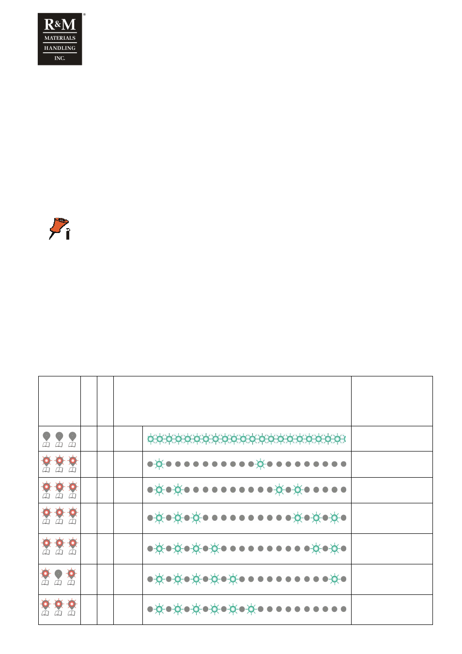
Red LED
OFF, Blink or
ON
W
a
rn
in
g
F
a
u
lt
Green LED
OFF, Blink or ON
Denoting code number
ON
Normal operation
X
Blink
Once
1
X
Blink
Twice
2
X
Blink
Three
times
3
X
Blink
Four
times
4
X
Blink
Five
times
5
X
Blink
Six
times
6