Prokit's Industries MT-3120 User Manual
Page 6
2A Mini Autorange Clamp Meter
user manual
20
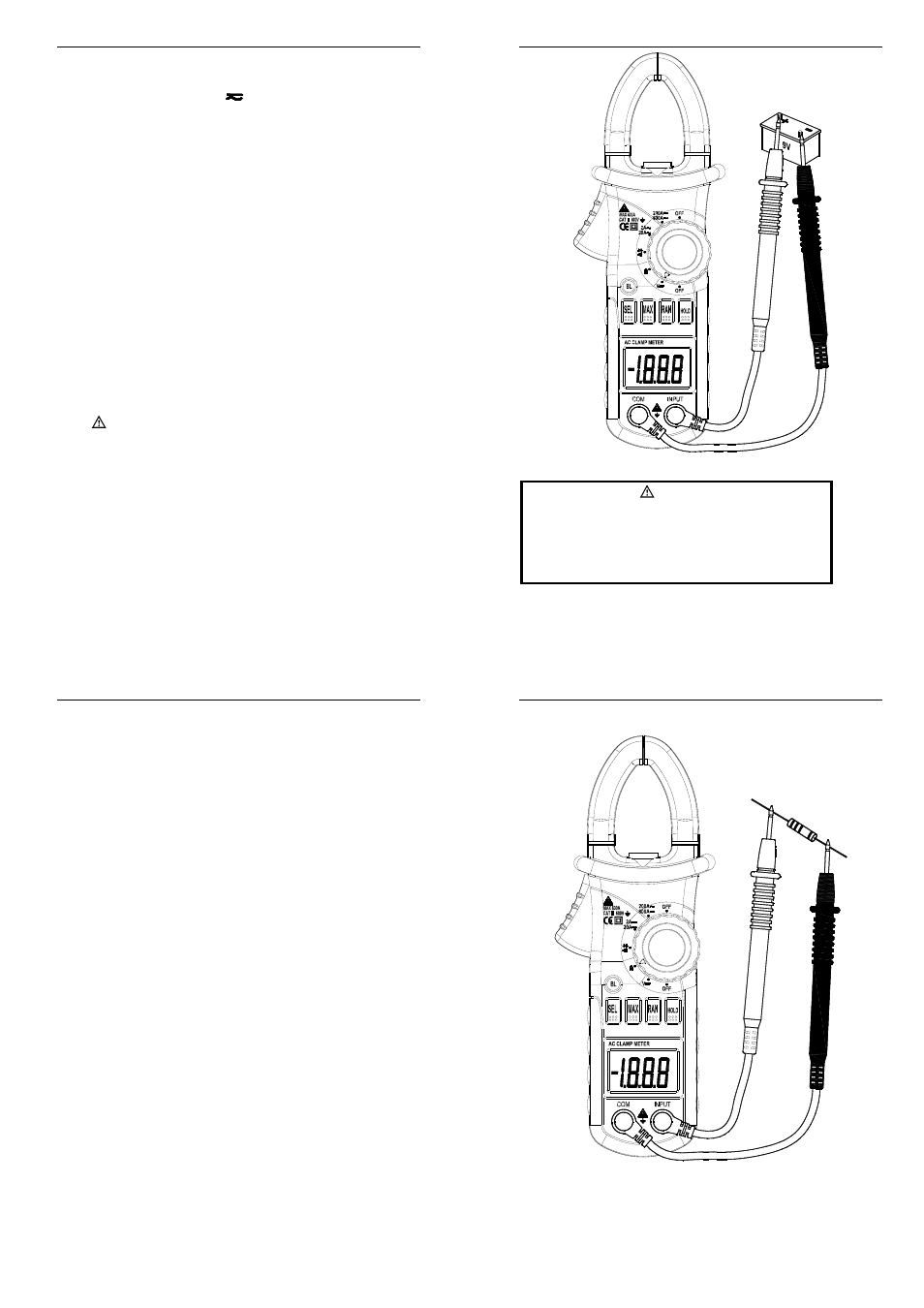
4.10.1 Plug the black test lead into the COM jack and the red test lead into the
INPUT jack.
4.10.2 Set the rotary selector to the V
range position.
4.10.3 Press the "SEL" as switch to DC V measurement. If necessary, press the
“RAN” button to choose the manual range mode.
4.10.4 Connect the test leads to the voltage source or load terminals for
measurement.
4.10.5 Take the reading on the LCD. The polarity symbol denotes the polarity of
the end connected by the red test lead.
NOTE:
1) At small voltage range, unsteady readings will appear before the test leads
contact the circuit. This is normal because the meter is highly sensitive.
When the test leads contact the circuit, the true reading will be shown.
2) Under the manual range mode, when only ‘OL’ or ‘-OL’ is shown on the LCD,
it means the measurement has exceeded the range. A higher range should
be selected.
3) Under the manual range mode, when the scale of the value to be measured
is unknown beforehand, select the highest range first and lower the range
gradually.
4) “
” means the maximum input voltage is 600V DC.
2A Mini Autorange Clamp Meter
user manual
21
4.11 MEASURING RESISTANCE
WARNING
Beware of Electrocution.
When measuring in-circuit resistance, make sure that the
power of the circuit under test has been turned off and that
all capacitors have been fully discharged.
2A Mini Autorange Clamp Meter
user manual
22
4.11.1 Plug the black test lead into the COM jack and the red test lead into the
INPUT jack.
4.11.2 Set the rotary selector to the
Ω range position.
4.11.3 If necessary, press the “RAN” button to choose the manual range mode.
4.11.4 Connect the test leads to the ends of the resistor or circuit for
measurement.
4.11.5 Take the reading on the LCD.
NOTE:
1) At the manual range mode, when only ‘OL’ is shown on the LCD, it means
the measurement has exceeded the range. A higher range should be
selected.
2) When the input is open, ‘OL’ will appear on the LCD to indicate that the
range has been exceeded.
3) For measuring resistance above 1MΩ, it may take a few seconds to get a
steady reading. This is normal for high resistance reading.
2A Mini Autorange Clamp Meter
user manual
23
4.12 TESTING DIODE
4.12.1 Plug the black test lead into the COM jack and the red test lead into the
INPUT jack.