Prokit's Industries MT-3120 User Manual
Page 5
2A Mini Autorange Clamp Meter
user manual
16
4.7 PREPARATING FOR MEASUREMENT
4.7.1 Switch on the power by turning the rotary selector. If the battery voltage is
lower than 3.6V, the “
” symbol will appear and the batteries should be
replaced.
4.7.2 The “
” symbol shows that the input voltage or current should not
exceed the specified value in order to protect the internal circuit from
damage.
4.7.3 Turn the rotary selector to the required function and range to be measured.
Under the manual mode, choose the highest range when the value scale to
be measured is unknown.
4.7.4 Connect the common test lead first and then the charged test leads when
making connection. Take away the charged test lead first when
disconnecting.
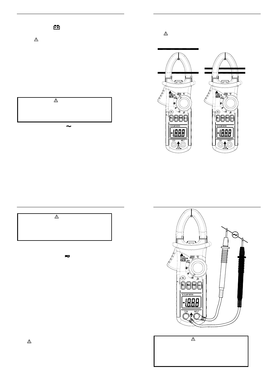
4.8 MEASURING AC CURRENT
WARNING
Beware of Electrocution.
Ensure that the test leads are disconnected from the meter
before making current clamp measurements.
4.8.1 Set the rotary selector to the A
range position.
4.8.2 If necessary, press the “RAN” button to choose the manual range mode.
4.8.3 Press the trigger to open jaw. Fully enclose only one conductor.
4.8.4 Take the reading on the LCD.
NOTE:
1) For right results, do not enclose more than one conductor in the jaw.
2) For optimum results, center the conductor in the jaw.
3) At the manual range mode, when only ‘OL’ is shown on the LCD, it means
the measurement has exceeded the range. A higher range should be
2A Mini Autorange Clamp Meter
user manual
17
selected.
4) Under the manual range mode, when the scale of the value to be measured
is unknown beforehand, set the range to the highest.
5) “
” means the maximum input current is 600A rms AC.
Correct
Incorrect
2A Mini Autorange Clamp Meter
user manual
18
4.9 MEASURING AC VOLTAGE
WARNING
Beware of Electrocution.
Pay special attention to avoid electric shock when measuring
high voltage.
Do not input the voltage which more than 600V rms AC.
4.9.1 Plug the black test lead into the COM jack and the red test lead into the
INPUT jack.
4.9.2 Set the rotary selector to the V
range position, then the meter at the AC
V measurement mode.
4.9.3 If necessary, press the “RAN” button to choose the manual range mode.
4.9.4 Connect the test leads to the voltage source or load terminals for
measurement.
4.9.5 Take the reading on the LCD.
NOTE:
1) At small voltage range, unsteady readings may appear before the test leads
contact the circuit. This is normal because the meter is highly sensitive.
When the test leads contact the circuit, the true reading will be shown.
2) At the manual range mode, when only ‘OL’ is shown on the LCD, it means
the measurement has exceeded the range. A higher range should be
selected.
3) At the manual range mode, when the scale of the value to be measured is
unknown, select the highest range first and lower the range gradually.
4) “
” means the maximum input voltage is 600V rms AC.
2A Mini Autorange Clamp Meter
user manual
19
4.10 MEASURING DC VOLTAGE
WARNING
Beware of Electrocution.
Pay special attention to avoid electric shock when measuring
high voltage.
Do not input the voltage which more than 600V DC.