Warning, Installation to wall stud – Peerless-AV DS-VW660-2X2 - Installation User Manual
Page 4
4 of 10
ISSUED: 09-22-11 SHEET #: 125-9248-3 04-01-13
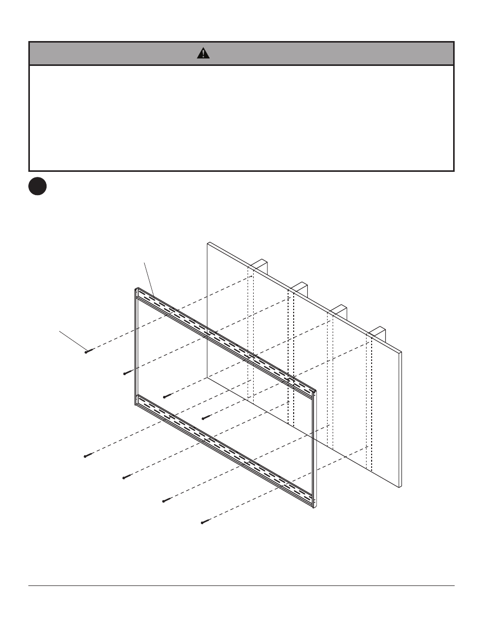
Installation to Wall Stud
Use a stud finder to locate the edges of the stud. Use of an edge-to-edge stud finder is highly recommended.
Based on their edges, draw a vertical line down the stud center. Place wall plate assembly on wall as a template.
Level plate, and mark the center of the eight mounting holes. Make sure that the mounting holes are on the stud
center line. Drill eight 5/32" (4 mm) dia. holes 2-1/2" (65 mm) deep. Make sure that the wall plate assembly is
level, secure it using eight #14 x 2.5" wood screws (
I) as shown below.
NOTE: When installing DS-VW660-2x2 two additional #14 x 2.5" wood screws (I) are required.
• Installer must verify that the supporting surface will safely support the combined load of the equipment and all
attached hardware and components.
• Tighten wood screws so
that wall plate is firmly attac
hed, but do not overtighten. Overtightening can damage the
screws, greatly reducing their holding power.
• Never tighten in excess of 80 in. • lb (9 N.M.).
• Make sure that mounting screws are anchored into the center of the stud. The use of an "edge to edge" stud finder
is highly recommended.
• Hardware provided is for attachment of mount through standard thickness drywall or plaster into wood studs. Install-
ers are responsible to provide hardware for other types of mounting situations.
WARNING
2
A
I