Warning, Caution, Installing and removing flat panel screen 4 – Peerless-AV PT630 - Installation User Manual
Page 8: Fig. 4.3
8 of 34
ISSUED: 11-19-07 SHEET #: 202-9245-2 07-28-09
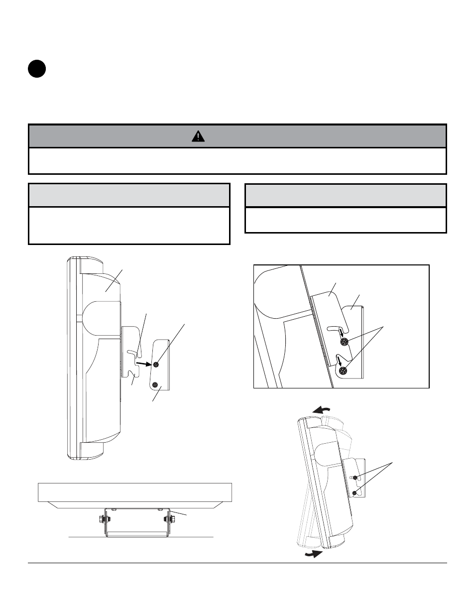
Position top slots of mounting plate (
B) onto phillips hex head screws on wall plate (A) as shown in figure 4.1.
NOTE: Sides of mounting plate (B) must be outside of wall plate (A) on both sides as shown in figure 4.2.
Guide slots of mounting plate onto four phillips hex head screws as shown in figure 4.3.
Push or pull from top or bottom of screen to adjust tilt as shown in figure 4.4. The tilt can be adjusted to a maximum
of 15° forward or 5° backward. To lock the screen into the desired tilt position, tighten phillips hex head screws on
both sides of mount.
To remove screen from mount, loosen screws one full turn and lift screen off of mount.
Installing and Removing Flat Panel Screen
4
SCREEN
• Do not lift more weight than you can handle. Use additional man power or mechanical lifting equipment to safely
handle placement of the screen.
WARNING
• Be careful not to pinch fingers when pushing screen
from the bottom.
CAUTION
• Do not tighten screws with excessive force.
Overtightening can cause damage to mount. Tighten
screws to 40 in. • lb (4.5 N.M.) maximum torque.
CAUTION
fig. 4.4
fig. 4.1
fig. 4.2
SCREEN
WALL
SIDES OF MOUNTING
PLATE (
B) ON OUTSIDE
OF WALL PLATE (
A)
TOP VIEW
A
B
PHILLIPS HEx
HEAD SCREW
SLOT
A
B
fig. 4.3
PHILLIPS HEx
HEAD SCREWS
PHILLIPS HEx
HEAD SCREWS
© 2009, Peerless Industries, Inc. All rights reserved.
All other brand and product names are trademarks or registered trademarks of their respective owners.
Peerless Industries, Inc.
3215 W. North Ave.
Melrose Park, IL 60160
www.peerlessmounts.com