PowerWalker VFI 30000TP 3_3 BE User Manual
Page 30
25
Routing of communication cables or data lines should be kept separate from the UPS input,
output, and external battery cables.
Use cable cross section and protective device specification
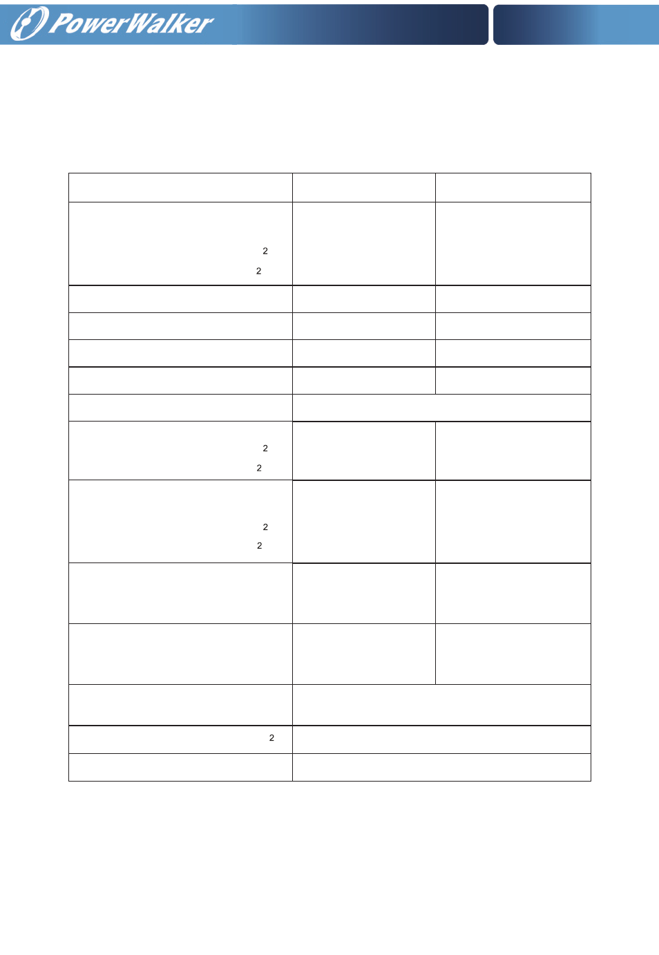
Model VFI 30000TP 3/3 BE/BI VFI 40000TP 3/3 BE/BI
Rectifier Input L1, L2, L3, N,
Bypass Input L1, L2, L3, N,
min. conductor cross section[mm ] 10 16
max. possible cross section[mm ] 35 35
Rectifier Input L1, L2, L3, N breaker (A) 80A 230VAC 100A 230VAC
Bypass Input L1, L2, L3, breaker (A) 80A 230VAC 100A 230VAC
Rectifier Input fuse (A) 80A 250VAC 100A 250VAC
Bypass Input fuse 80A 250VAC 100A 250VAC
Output L1, L2, L3, N,
min. conductor cross section[mm ] 10 16
max. possible cross section[mm ] 35 35
External Battery Cabinet Positive
pole(+),Neutral pole,Negative pole (-),
min. conductor cross section[mm ] 16 25
max. possible cross section[mm ] 35 35
External Battery Cabinet Fuse (A) in
Positive pole(+),Neutral pole,
Negative pole (-),
120A 250VAC 150A 250VAC
External Battery Cabinet breaker
(A) in Positive pole(+),Neutral
pole,Negative pole (-),
120A 250VAC 150A 250VAC
Protective Earthing conductor [mm ] Max 35
60A 250V AC Clearance distances:>=1.4mm
Break time<=15s
Backfeed protection device
Torque for fixing above terminals 2.8-3 Nm
Internal battery switch 125A 690VAC