PowerWalker VFI 1000T LCD User Manual
Page 20
17
(6) The red wire is connected to the "+" terminal of the battery. The
black wire is connected to the "-" terminal of the battery. (Note:
the green/yellow wire is grounded for protection purpose.)
(7) Make sure the wires are fasten, install the terminal block cover on
the rear panel of the UPS.
(8) Connect the UPS to the load. Then, turn on the mains switch or
connect the power cord of the UPS to utility power supply, the
battery would start to be charged.
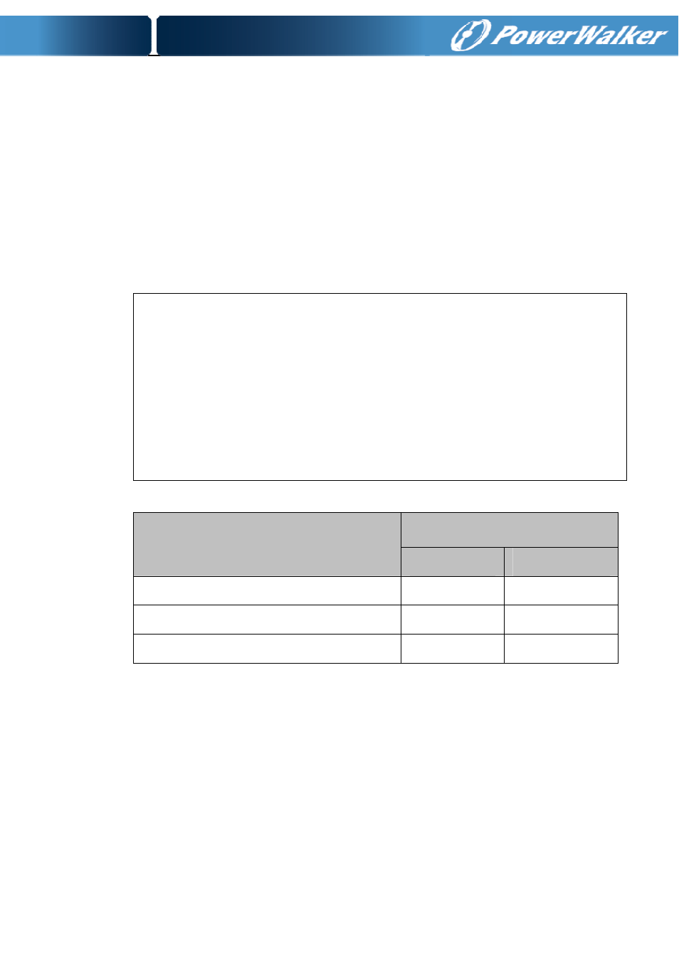
Model No.
DC breaker
VOLTAGE
CURRENT
PowerWalker VFI 1000T LCD L
48Vac
50A
PowerWalker VFI 2000T LCD L
125Vdc
40A
PowerWalker VFI 3000T LCD L
125Vdc
60A
The Caution!
A DC breaker must be connected between the UPS and
external battery.
The Caution!
The output sockets of the UPS system may still be electrically
live even if the power supply system has been disconnected or
the Bypass switch is on “OFF” position.