Power supply requirements, Communicating with the vfg9000-can option card – B&B Electronics VFG9000-CAN - Quick Start Guide User Manual
Page 3
POWER SUPPLY REQUIREMENTS
NEW AND EXISTING INSTALLATIONS
The VFG9000-CAN option card draws all of its power from the main board
of the Fieldbus Gateway. The specifications of the Fieldbus Gateway account
for the power needs of an option card.
COMMUNICATING WITH THE VFG9000-CAN
OPTION CARD
CONFIGURING A VFG9000-CAN OPTION CARD
The VFG9000-CAN is configured using Fieldbus Gateway Manager
software. Updates to the software for new features and drivers are posted on the
website as they become available. By configuring the VFG9000-CAN using the
latest version of the software, you are assured that your unit has the most up-to-
date feature set. The software can configure the VFG9000-CAN through the
RS232 PGM port, USB port, Ethernet port, or CompactFlash socket on your
Fieldbus Gateway. Additional information can be found in your Fieldbus
Gateway hardware bulletin and the Fieldbus Gateway Manager user manual.
CANopen PORT PROTOCOLS
The VFG9000-CAN option card has one CANopen port. This port may be
configured for various CANopen protocols. Check www.bb-elec.com for
currently supported protocols.
VFG9000-CAN PORT PIN OUTS
Must use only NEC Class 2 or Limited Power Source (LPS) rated power
supply.
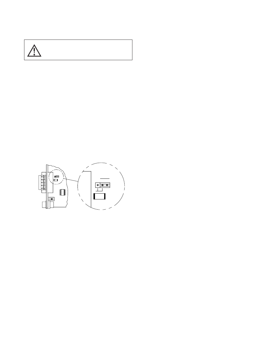
TERMINATION RESISTOR
An onboard termination resistor is selectable via a jumper setting. The
termination resistor is rated for 124Ω at 1W. If a different termination resistance
is desired, choose the jumper setting for no termination resistor and connect
your own termination resistor between positions 2 and 4 of the five position
connector.
GND
Position 1 of the pluggable connector provides a CAN ground connection.
This terminal is isolated from the Fieldbus Gateway.
CAN-
Position 2 of the pluggable connector provides the CAN- bus line (active
low). This terminal is isolated from the Fieldbus Gateway.
SHLD (OPTIONAL CAN SHIELD)
Position 3 of the pluggable connector is provided for optional shield
connections. This position is available only to tie shield wires together or to
earth ground. There is no internal connection to earth ground. The SHLD
position is not connected to any circuitry internal to the VFG9000-CAN option
card or Fieldbus Gateway.
CAN+
Position 4 of the pluggable connector provides the CAN+ bus line (active
high). This terminal is isolated from the Fieldbus Gateway.
V+ (OPTIONAL 24 VDC)
Position 5 of the pluggable connector is provided for optional 24 VDC
connections. This position is available only to tie 24 VDC wires together. The
VFG9000-CAN card neither provides 24 VDC power nor uses 24 VDC power
through this connection. The V+ position is not connected to any circuitry
internal to the VFG9000-CAN option card or Fieldbus Gateway.
LED
The LED will illuminate green when the VFG9000-CAN option card
establishes communication with other CANopen devices (RUN). The LED will
illuminate red if no communications have been established with other CANopen
devices (ERROR).
TROUBLESHOOTING YOUR VFG9000-CAN OPTION CARD
If for any reason you have trouble operating, connecting, or simply have
questions concerning your new VFG9000-CAN option card, contact B&B
Electronics’ technical support. For contact information, refer to the back page
of this bulletin for phone and fax numbers.
Web Site: http://www.bb-elec.com
3
SHLD
V+
CAN+
GND
CAN-
DEFAULT
TERMINATION RESISTOR
(OFF)
ON
WARNING - EXPLOSION HAZARD - DO NOT DISCONNECT
WHILE CIRCUIT IS ALIVE UNLESS AREA IS KNOW TO BE
NON-HAZARDOUS.