B&B Electronics 485LP9TB - Datasheet User Manual
B&B Electronics Accessories communication
Document No. 485LP9TB0812 - pg. 1/2
www.bb-elec.com
International Office: 707 Dayton Road PO Box 1040 Ottawa, IL 61350 USA 815-433-5100 Fax 433-5104
European Office: Westlink Commercial Park Oranmore Co. Galway Ireland +353 91 792444 Fax +353 91 792445
P
R
O
D
U
C
T
I
N
F
O
R
M
A
T
IO
N
B
&B
ELEC
TR
ON
ICS
Port Powered RS-232 to RS-485 Converter
Model 485LP9TB
The 485LP9TB is a port-powered two-channel RS-232 to RS-485
converter. It converts TD and RD RS-232 lines to balanced RS-485 signals.
The unit can be powered from the RS-232 handshake lines, DTR and RTS. If
port powering the unit, one of these handshake lines must be asserted (high) in
order to power the unit (See Table 1). DTR must be asserted to receive data. The RS-485 driver is enabled when
RTS is asserted and disabled when RTS is disasserted. The RS-485 receiver is disabled when the driver is
enabled and is enabled when the driver is disabled.
In order to maximize the amount of power available to the RS-485 driver, the RS-232 handshake lines
are not looped back (tied together). As a result the following handshake lines will appear as disasserted (low):
CTS, DCD, and DSR. Care should be taken to insure that any software being used doesn’t require any of these
handshake lines be asserted. If existing software requires any of the handshake lines to be asserted, you can loop
back the required handshake lines in your cable.
Table 1
* NOTE: Low = disasserted and High = asserted
Connections
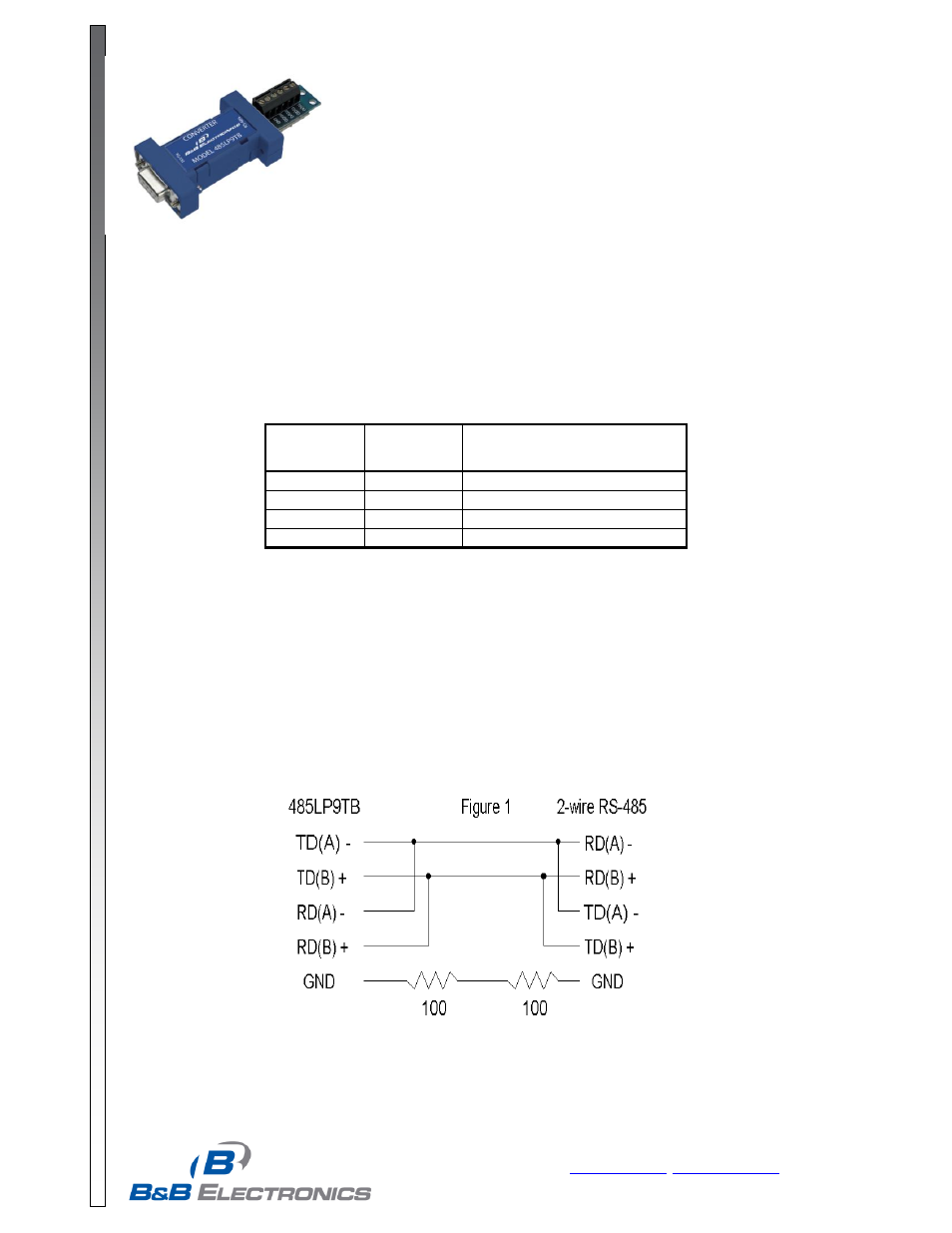
A typical two wire RS-485 connected is shown in Figure 1. Regardless of the system, the 485LP9TB must
be connected with the proper polarity. With no data is being sent and the driver enabled, the RS-232 line should
be negative and the TD(A) should be negative with respect to TD(B).
Proper operation of any RS-485 system requires the presence of a signal return path between the signal
grounds of the equipment at each end of an interconnection. This circuit reference may be established by a third
conductor connecting the common leads of devices, or it may be provided by connections in each equipment to
an earth reference. When the circuit reference is provided by a third conductor, the connection between the signal
grounds and the third conductor should contain some resistance (e.g. 100 ohms) to limit circulating currents when
other ground connections are provided for safety.
Biasing Resistors
The biasing resistors for the RS-485 receiver are 4.7K Ohm resistors. These resistors are labeled R1 and
R6 (See Figure 2). Refer to B&B Electronics RS-422/485 Application Note for further information on biasing.
RTS
State
DTR
State
Functions Possible
(when port powering unit)
Low
Low
none
Low
High
Receive
High
Low
Transmit
High
High
Transmit