Power supply requirements, Communicating with the vfg9000-pbdp option card, Software/unit operation – B&B Electronics VFG9000-PBDP - Quick Start Guide User Manual
Page 3
POWER SUPPLY REQUIREMENTS
NEW AND EXISTING INSTALLATIONS
The VFG9000-PBDP option card draws all of its power from the main board
of the Fieldbus Gateway. The specifications of the Fieldbus Gateway account
for the power needs of an option card.
COMMUNICATING WITH THE VFG9000-PBDP
OPTION CARD
CONFIGURING THE VFG9000-PBDP OPTION CARD
The VFG9000-PBDP is configured using Fieldbus Gateway Manager software.
Updates to the software for new features and drivers are posted on the website
as they become available. By configuring the VFG9000-PBDP using the latest
version of the software, you are assured that your unit has the most up-to-date
feature set. Additional information can be found in your hardware bulletin and
also in the Fieldbus Gateway Manager user manual.
To enable the option card, click on the left hand pane of the Communications
window in Fieldbus Gateway Manager and highlight the icon that represents the
Fieldbus Gateway. In the right pane, click the Option Card Selection’s Edit
button to show the selection dialog, and choose the PROFIBUS option card
from the list. The PROFIBUS option card will then appear in the left hand pane,
installed in the tree of available ports.
CONFIGURING THE DRIVER
To select a driver, click on the left hand pane of the Communications window
and highlight the PROFIBUS Interface icon. In the right hand pane, click the
Driver Selection Edit button to show the Driver Selection dialog and select the
PROFIBUS DP driver from the list.
The Station Address of the PROFIBUS node is the only property that needs
to be configured. This should be a unique address on the PROFIBUS Network
in the range 1..125.
CONFIGURING THE DATA TAGS
A PROFIBUS master exchanges data with slaves as separate input and output
blocks. Data transfer direction is described with respect to the PROFIBUS
Network such that input data is transferred to the network, or written by the
Fieldbus Gateway and output data is transferred from the network or read by the
Fieldbus Gateway. This is important when it comes to configuring the data
access for each tag mapped to a PROFIBUS data block.
MAPPING TAGS TO PROFIBUS
PROFIBUS data blocks have no concept or knowledge of data type or
structure – they are described by a size in bytes. Fieldbus Gateway Manager’s
tag-based approach to data allows for data of mixed type, bytes, 16-bit words,
32-bit words and 32-bit floating point numbers to be mapped into a single data
block. To map a data tag to a PROFIBUS data block, click in the left hand pane
of the Data Tags window, highlight the required Data Tag icon. In the right hand
pane click the Data Mapping button and select the PROFIBUS device to show
the Select Address for PROFIBUS DP dialog.
The Block Type defines whether the tag will be read from (Output Block) or
written to (Input Block) the PROFIBUS network
The Data Offset is the byte address of the Data Tag within the Data Block
The Data Type is the actual size in bytes of the data that will be mapped into
the Data Block.
SOFTWARE/UNIT OPERATION
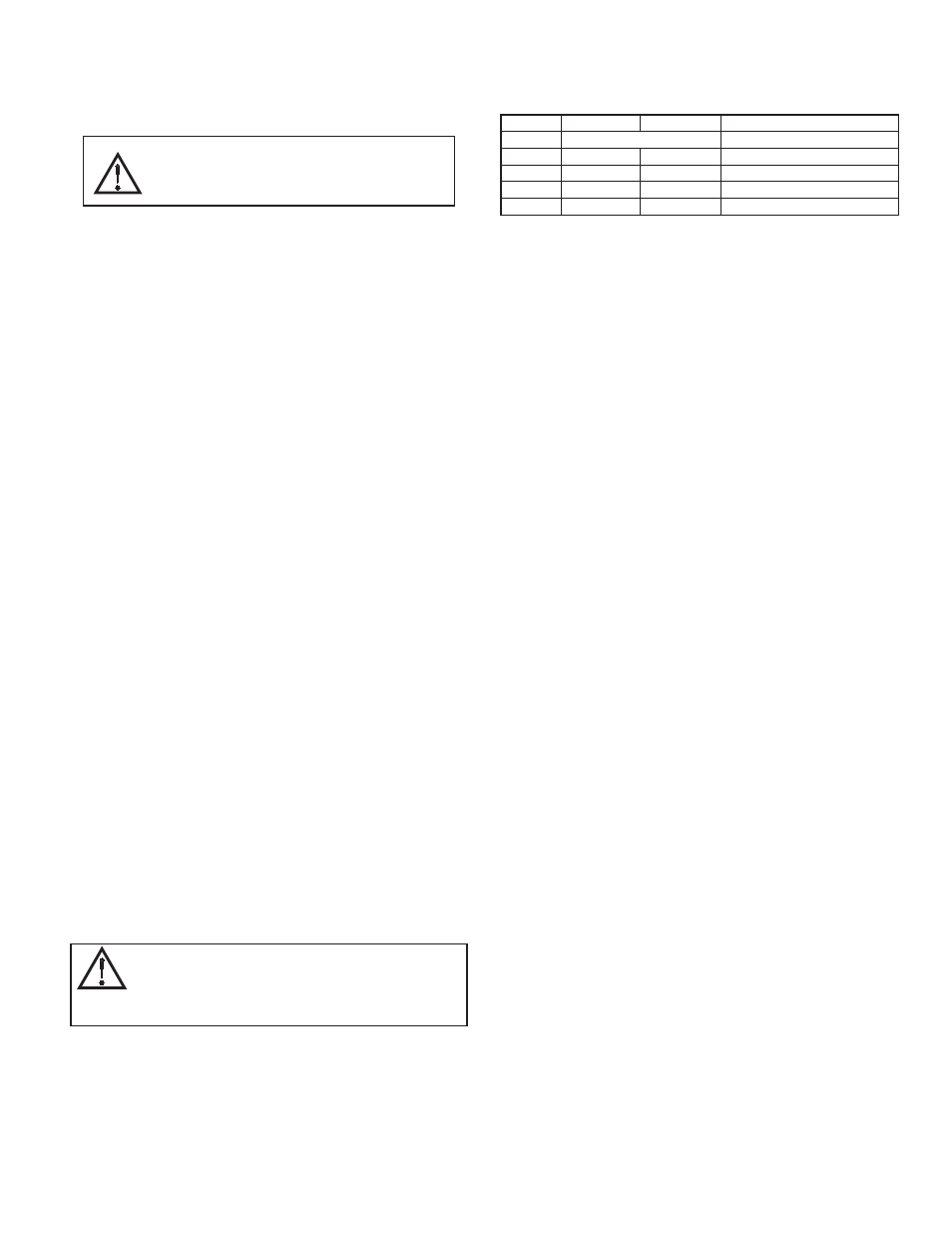
LEDS
The card has 3 LEDs visible on the front of the option card that provide status
information, described in Table 1.
TROUBLESHOOTING YOUR VFG9000-PBDP OPTION CARD
If for any reason you have trouble operating, connecting, or simply have
questions concerning your new VFG9000-PBDP option card, contact B&B
Electronics’ technical support. For contact information, refer to the back page
of this bulletin for phone and fax numbers.
Web Site: http://www.bb-elec.com
DATA (Red)
WD (Green)
DP (Red)
DESCRIPTION
OFF
Baud Search
OFF
OFF
ON
Baud Control
OFF
SLOW FLASH FAST FLASH
OFF
FAST FLASH SLOW FLASH
ON
OFF
OFF
Data Exchange
SLOW ALTERNATING FLASH
Waiting for Parameter Telegram
Waiting for Configuration Telegram
CONFIGURING DATA ACCESS IN
FIELDBUS GATEWAY MANAGER
As described, Data Tags are mapped to either an Input Block
and are Write only, or an Output Block and are Read Only. The
Access must be selected to reflect this.
3
WARNING - EXPLOSION HAZARD - DO NOT DISCONNECT
WHILE CIRCUIT IS ALIVE UNLESS AREA IS KNOW TO BE
NON-HAZARDOUS.