Dip switch setting, Pinouts – B&B Electronics USOPTL4-4P - Quick Start Guide User Manual
Page 2
P#8505R002_ULINX 2&4 PORT_0712qsg
5
Dip Switch Setting
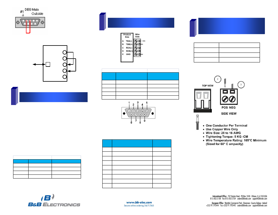
TDA(-)
TDB(-)
RDA(-)
RDB(-)
GND
USB
TO PC
RS-485
External Power Option:
USO9ML2-2P
10 to 30 VDC @ 3.0 W max.
USO9ML2-4P
10 to 30 VDC @ 5.0 W max.
USOPTL4-2P
10 to 30 VDC @ 3.0 W max.
USOPTL4-4P
10 to 30 VDC @ 5.0 W max.
Surrounding Air Ambient Temperature: 0 to 70° C
Dip Sw itch Settings
Sw itch
Off (left)
On (right)
1
RS-422
RS-485
2
ECHO ON
ECHO OFF
3
4-Wire
2-Wire
4
4-WIre
2-Wire
6
Pinouts
RS485 Pinout (Term inal Blocks)
Term inal
Position RS-485, 4 Wire
RS-485, 2 Wire
A
Transmit TDA (-) Output
Data A (-) Input / Output
B
Transmit TDB (+) Output
Data B (+) Input / Output
C
Receive RDA (-) Input
Data A (-) Input / Output
D
Recieve RDB (+) Input
Data B (+) Input / Output
E
Ground
Ground
Note: For models with selectable RS-422/485 configurations
Dip switches allow the module to be configured for two-wire or
four-wire, RS-422 or RS-485 modes. In two-wire mode the TDA (-)
and RDA (-) are tied together and so are TDB (+) and RDB (+),
making multi-dropping this converter into an existing network easy.
7
Optional External Power for
Optically Isolated Units
1. Loosen the screw to open the terminal block lead clamp.
2. Insert the power lead. TB will accept 28-16 AWG wire.
3. Tighten the screw to close the terminal block lead clamp. Ensure
the clamp holds the lead securely. However, do not over tighten.
NOTE: For Replacement Terminal Block, Order Part #7444.
NOTE: To remove drivers from a PC, there is an Uninstall
reference document on the CD ROM.
RS-232
RS-232 Pinout (DB9 Male DTE)
PIN
Signal Name
RS-232
Signals
1
DCD (Data Carrier Detect)
Input
2
RD (Receive Data)
Input
3
TD (Transmit Data)
Output
4
DTR (DTE Ready)
Output
5
SG (Signal Ground)
Ground
6
DSR (DCE Ready)
Input
7
RTS (Request to Send
Output
8
CTS (Clear to Send)
Input
9
RI (Ring Indicator)
Input