B&B Electronics IASW5P - Datasheet User Manual
Product information b&b electronics
IASW5P-0605ds - 1/2
© 2004 by B&B Electronics. All rights reserved.
International Headquarters: 707 Dayton Road PO Box 1040 Ottawa, IL 61350 USA
815-433-5100 Fax 433-5104 www.bb-elec.com [email protected] [email protected]
European Headquarters: Westlink Commercial Park Oranmore Co. Galway Ireland
+353 91 792444 Fax +353 91 792445 www.bb-europe.com [email protected] [email protected]
PRODUCT INFORMATION
B&B ELECTRONICS
Model IASW5P
5-Port Industrial 10/100
Ethernet Switch
CE
Description
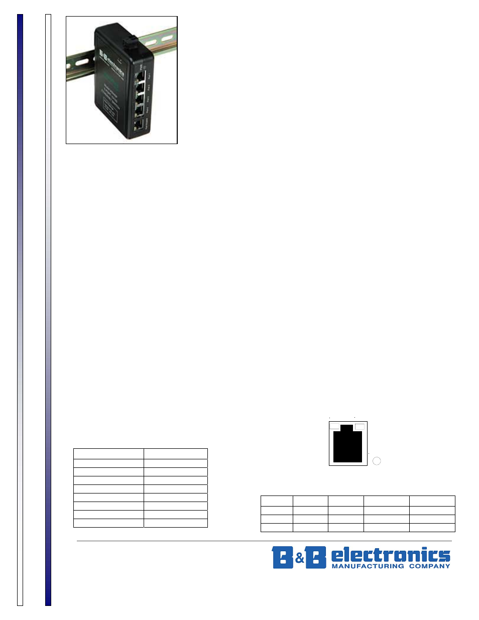
ModeI IASW5P is a 5-port 10/100 switch designed for the not-so-friendly industrial environment. The unit is housed
in a rugged ABS enclosure ready to be mounted on a DIN rail or panel. The switch is an unmanaged Layer 2 switch
that provides auto MDI/MDIX crossover for easy plug-and-play applications.
LEDs indicate power, speed and link/activity for easy visual diagnostics. External power supply is connected to a 2-
position pluggable terminal block. A 9-30 VDC power supply is required and available. B&B Electronics’ power supply model
232PS4, 485PS4 or PS5R-A12 is required, not included.
Features
• Fully IEEE 802.3 and 802.3u compliant
• 5-port unmanaged Layer 2 switch
• Auto detecting 10BaseT/100BaseTX
• Auto MDI/MDIX crossover for plug and play
• DIN rail mountable
• Panel mountable
• Wide power input 9-30 VDC
Applications
Industrial
automation
Process
control
Ethernet
I/O
Motion
control
Remote data acquisition
Environmental control
Communications gateway
Machine
monitoring
PLC and operator interface
Factory floor Ethernet networks
Connections
Standard RJ45 female connectors are provided. Standard RJ45 plug cables are all that is necessary to connect your
devices to the unit since the switch supports auto crossover. External power supply is connected using the 2-position
pluggable terminal block for convenience. Table 1 shows the RJ45 pinouts and Table 2 shows the LED indicators.
Table 1
Pin Number
Signal
1 TX+
2 TX-
3 RX+
4
not used
5 not
used
6 RX-
7 not
used
8 not
used
Table 2
LED Color On
Off
Blinking
SPD orange 100
10
reset/error
LNK green link no
link
data
PWR red power
no
power NA
SPD
LNK
PWR