B&B Electronics 485OPDRI-PH - Quick Start Guide User Manual
Quick start guide
Documentation Number – p/n 8932r001 485OPDRI-PH-1712qsg
©2010 B&B Electronics Manufacturing Company
International Headquarters: 815-433-5100 www.bb-elec.com
European Headquarters: +353 91 792444 www.bb-europe.com
1
1
.
.
C
C
h
h
e
e
c
c
k
k
f
f
o
o
r
r
R
R
e
e
q
q
u
u
i
i
r
r
e
e
d
d
H
H
a
a
r
r
d
d
w
w
a
a
r
r
e
e
ILinx 485OPDRI-PH Isolated Repeater
This Quick Start Guide
Additional Items Required but not included
o A 10 to 48 VDC Power Supply. Repeater draws
2.3W Max.
2
2
.
.
I
I
n
n
f
f
o
o
r
r
m
m
a
a
t
t
i
i
o
o
n
n
–
–
U
U
L
L
C
C
l
l
a
a
s
s
s
s
1
1
D
D
i
i
v
v
2
2
1. Refer to Nonincendive Field Wiring Apparatus
Control Drawing. for important information.
2. Power, Input / output (I/O) wiring for the end use
enclosure must be in accordance with Class 1
Division 2 wiring methods (Article 501.10(B) of the
National Electric Code, NFPA 70) and in
accordance with the local authority having
jurisdiction.
3. Maximum ambient air temperature 85°C.
4. Temperature rating of field installed conductors
105°C. Use Copper Wire Only.
5. These devices must be installed in end use
enclosure suitable for the location.
6. WARNING
– EXPLOSION HAZARD
SUBSTITUTION OF COMPONENTS MAY IMPAIR
SUITABILITY FOR CLASS 1, DIVISION 2.
7. WARNING
– EXPLOSION HAZARD: DO NOT
DISCONNECT EQUIPMENT UNLESS POWER
HAS BEEN SWITCHED OFF OR THE AREA IS
KNOWN TO BE NON-HAZARDOUS.
8. WARNING
– THIS APPARATUS IS SUITABLE
FOR USE IN CLASS 1 DIVISION 2, GROUPS A,
B, C, AND D OR NONHAZARDOUS LOCATIONS
ONLY.
Quick Start Guide
ILinx 485OPDRI-PH
Triple Isolated RS-422/485
Repeater
3
3
.
.
F
F
r
r
o
o
n
n
t
t
&
&
B
B
a
a
c
c
k
k
P
P
a
a
n
n
e
e
l
l
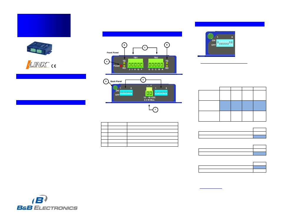
A
Power LED
Red, ON When Power Applied
B
Data LEDs
Green. LEDs Flash When Data is on
Port.
C
422/485 TB
5 Position, Removable
D
Ground Lug
Chassis Ground to Earth Ground
E
DIP Switch
Used to Configure
F
Power TB
2 Position, Removable
4
4
.
.
C
C
o
o
n
n
f
f
i
i
g
g
u
u
r
r
a
a
t
t
i
i
o
o
n
n
D
D
I
I
P
P
S
S
w
w
i
i
t
t
c
c
h
h
SWITCH POSITION 8 IS NOT USED
Highlighted settings indicate factory default.
Switch functions are identical for each port.
Communications Mode
Switch
1
2
3
4
RS-485
2-Wire
Half Duplex
ON
ON
ON
ON
RS-485
4-Wire
Full Duplex
ON
OFF
OFF
OFF
RS-422
Full Duplex
OFF
OFF
OFF
OFF
Built-in Termination Resistor
Switch
5
Use the 120Ω Built-in Termination
ON
Use External or No Termination
OFF
Built-in Transmit Bias Resistor
Switch
6
Use External or No Bias Resistor
ON
Use the 1.2K Ω Transmit Bias Resistor OFF
Built-in Receive Bias Resistor
Switch
7
Use External or No Bias Resistor
ON
Use the 1.2K Ω Receive Bias Resistor
OFF
For an explanation of RS-485 termination and biasing
requirements, refer to B&B Electronics’ RS-485
application note. This publication can be downloaded