B&B Electronics EIR-EXTEND - Quick Start Guide User Manual
Product overview, Set dip switch, Connect your power supply
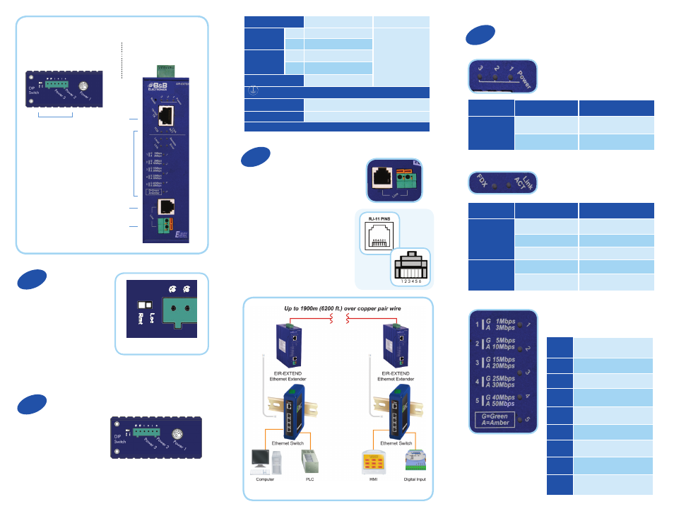
Product Overview
DIP Switch and
Power Options
Top View
Front View
Ethernet
In/Out
LED
Indicators
RJ11 In/Out
Copper Cable
In/Out
Set DIP Switch
Ethernet extenders work
in pairs. Set one as the local
(Loc) unit and the other as the
remote (Rem) unit. It doesn’t
matter which one is which.
The DIP switch is on top of the device.
Connect Your Power Supply
Only one power source
is required. Redundant
power is supported.
Plug In Your Cable
If you are using the terminal
block, straight or crossover
cable are both supported.
Installing new, shielded,
24 gauge copper wire
is recommended.
If using RJ11 cable, straight
or crossover cable are both
supported. (Only pins 3
and 4 are actually used.)
Note: Extender must be connected to a receiving extender or a network switch.
LED Status
Power LEDs
Ethernet over VDSL LEDs
Ethernet LEDs
Power 1
12VDC/350 mA
DC Jack
Power 2
+
12-30VDC/175 mA
Terminal Block
-
Power Ground
Power 3
+
12-30VDC/175 mA
-
Power Ground
Earth Ground
DIP Switch Assignment
Loc
The device operates in local mode
Rmt
The device operates in remote mode
Max power consumption 4.2 W
LEDs
State
Indication
Power 1
Power 2
Power 3
Steady
Power On
Off
Power Off
LEDs
State
Indication
Link/ACT
Steady
Valid network connection
established
Flashing
Transmitting or receiving data
Off
No network connection
FDX
Steady
Connection in full-duplex mode
Off
Connection in half-duplex
mode
Remote
Device is in remote mode
Local
Device is in local mode
Error
Error ocurred
Link
A valid VDSL connection is
established
1
Green, 1 Mbps, up to 1900 M
Amber, 3 Mbps, up to 1800 M
2
Green, 5 Mbps, up to 1900 M
Amber, 10 Mbps, up to 1800 M
3
Green, 15 Mbps, up to 1900 M
Amber, 20 Mbps, up to 1800 M
4
Green, 25 Mbps, up to 1900 M
Amber, 30 Mbps, up to 1800 M
5
Green, 40 Mbps, up to 1900 M
Amber, 50 Mbps, up to 1800 M
1
2
3
4