B&B Electronics EIR410-2SFP-T - Quick Start Guide User Manual
Quick start guide, Elinx gigabit ethernet switch eir41x-2sfp series, Items included
EIR41x-2SFP Series-1012qsg
Quick Start Guide
Elinx Gigabit Ethernet Switch
EIR41x-2SFP Series
Items Included
1
2
Hardware Installation
3
LED Chart
4
Ports
5
Installation Complete
o
Ethernet
Switch
o
CD with Support Manual
o
This Quick Start Guide
o
Panel Mount Bracket
1.
Select a mounting location and install the
switch onto a piece of DIN rail or use the
included panel mount brackets for wall or
panel mounting
2.
Connect power to the switch
12 to 48 VDC
If redundancy is desired be sure to
connect two separate power supplies by
using the two DC inputs on the terminal
blocks
If only one power input is used the Fault
LED will light (this is normal)
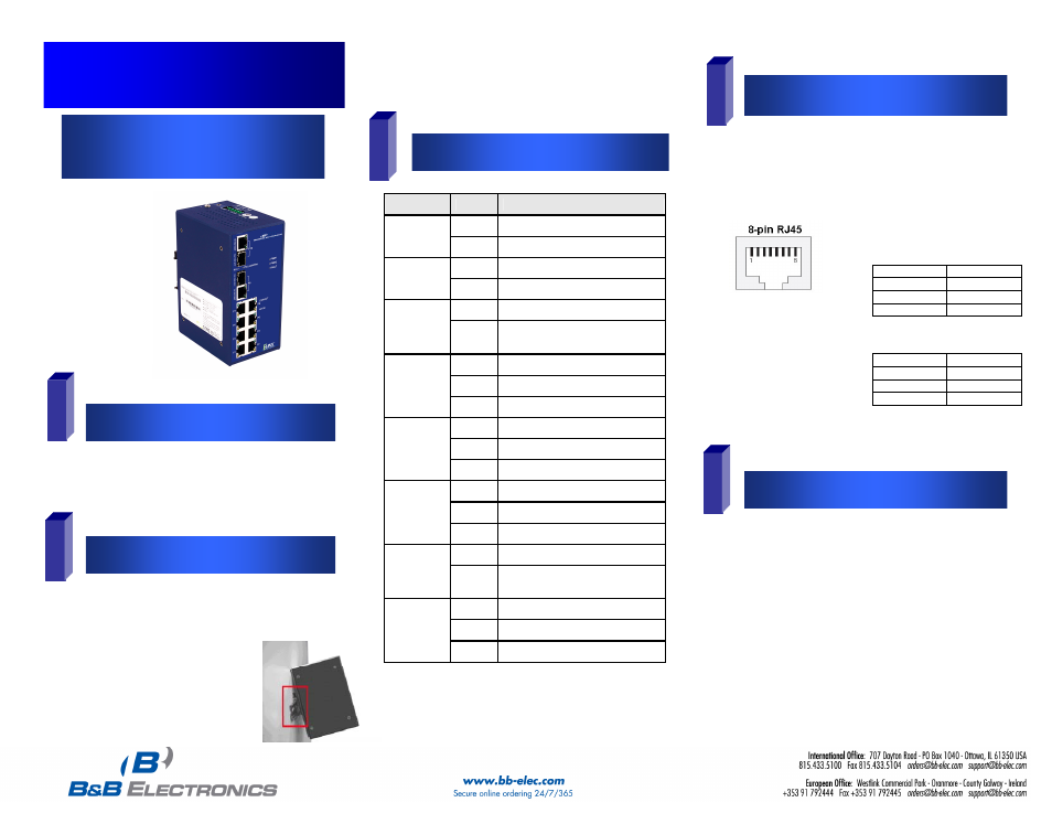
RJ-45 ports: The RJ-45 ports auto-sense for 10, 100 or 1000
Mbps devices connections. The auto MDI/MDIX feature
allows connections to switches, workstation and other
equipment without changing straight through or crossover
cabling. The charts below show the cable pin assignments
for straight through and crossover cables.
LED
Status
Description
Green
Power 1 is active
PWR1
Off
No power at input 1
Green
Power 2 is active
PWR2
Off
No power at input 2
Red
PWR1 or PWR2 has failed
Fault
Off
PWR1 & PWR2 are both active
or no power is applied
Green
Connected to network
Blinking
Networking is active
10/100
Copper
Upper LED
Off
Not connected to network
Yellow
Full duplex operation
Blinking
Collision of packets occurs
10/100
Copper
Lower LED
Off
Half duplex or no connection
Green
Connected to network
Blinking
Networking is active
Gigabit
Copper
Upper LED
Off
Not connected to network
Green
Operating at 1000M
Gigabit
Copper
Lower LED
Off
Operating at 10/100M or
disconnected
Green
SFP port is connected to network
Blinking
Networking is active
SFP
Link/Active
(100/1000)
Off
Not connected to network
MDI Cable Pinout
Pin Signal
1 Tx+
2 Tx-
3 Rx+
6 Rx-
MDI-X Cable Pinout
Pin Signal
1 Rx+
2 Rx-
3 Tx+
6 Tx-
1. Auto MDI/MDI-x is
supported. A straight
through or cross-over
cable may be used.
2. 10/100/1000 auto
negotiation and full/half-
duplex are supported.
1. When the network cables are attached and power
is applied, installation is complete.
2. The switch will automatically discover network
devices, populate its MAC address table, and
pass traffic to the appropriate ports.