B&B Electronics MESR900 Series - Fiber Models - Quick Start Guide User Manual
Quick start guide
Documentation Number PN 8164R4 MESR9xx-0712-qsg
C
C
h
h
e
e
c
c
k
k
f
f
o
o
r
r
A
A
l
l
l
l
R
R
e
e
q
q
u
u
i
i
r
r
e
e
d
d
H
H
a
a
r
r
d
d
w
w
a
a
r
r
e
e
Vlinx MESR9xx module
This Quick Start Guide
CD with Modbus Gateway Manager s/w and manuals
Network Cable(s) (not included)
Serial Cable(s) (not included)
Power Supply (not included)
S
S
e
e
t
t
u
u
p
p
t
t
h
h
e
e
M
M
o
o
d
d
b
b
u
u
s
s
G
G
a
a
t
t
e
e
w
w
a
a
y
y
S
S
o
o
f
f
t
t
w
w
a
a
r
r
e
e
Open Vlinx Manager: click StartProgramsB&B
ElectronicsVlinxModbus Gateway
ManagerConfiguration Manager.
The Device Discovery page opens.
L
L
o
o
g
g
i
i
n
n
Click Login. Password is blank from factory, no
password is necessary to operate the MESR unit.
The Configuration/General page appears.
Quick Start Guide
MESR 9xx Modbus Gateway
I
I
n
n
s
s
t
t
a
a
l
l
l
l
t
t
h
h
e
e
H
H
a
a
r
r
d
d
w
w
a
a
r
r
e
e
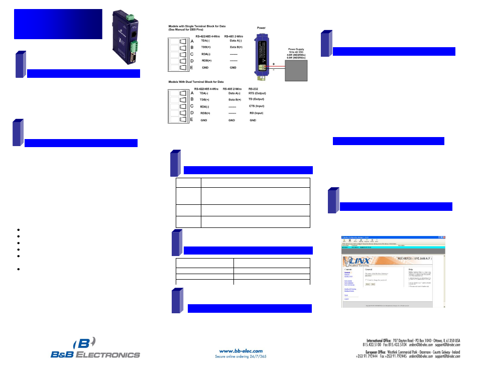
Connect a 10 to 48 VDC (58 VDC Max) power supply
(Sold separately). 4W for MESR90x, 6W for MESR92x
Connect the top RJ45 connector to a network drop
using a standard network cable (lower RJ45 is pass-
through Ethernet on the model shown below).
Connect the serial device(s):
o
RS-232 with DB9: straight-through for DCE
device, null modem for DTE device.
o
RS-232/422/485 with terminal blocks: see
Appendix D for pin outs.
UL Installation Information
One Conductor Per Terminal
Use Copper Wire Only
Wire Size: 28 to 16 AWG
Tightening Torque: 5 KG-CM
Wire Temperature Rating: 105 C Minimum (Sized for 60 C
Ampacity)
80 C Maximum Surrounding Ambient Air Temperature
SUITABLE FOR USE IN CLASS 1, DIVISION 2 GROUPS
A, B, C, AND D HAZARDOUS LOCATIONS, OR
NONHAZARDOUS LOCATIONS ONLY.
WARNING – EXPLOSION HAZARD – SUBSTITUTION
OF ANY COMPONENT MAY IMPAIR SUITABILITY FOR
CLASS 1, DIVISION 2.
2
1
L
L
E
E
D
D
S
S
t
t
a
a
t
t
u
u
s
s
LED
STATUS
Ready
Blinks if system is operating correctly, once per second
normally or three times per second for configuration mode
or when reset to factory defaults.
Port 1/
Port 2
On indicates serial port open, blinks when data present
(Port 2 present on 2 serial port units only).
E1/E2
On indicates Ethernet has a link, blinks with data traffic
(E2 present on 2 Ethernet port units only).
3
M
M
o
o
d
d
e
e
S
S
w
w
i
i
t
t
c
c
h
h
Hold in Mode switch for…
Result
0 to 2 seconds
Initiates a Hardware Reset
2 to 10 seconds
Enters Console Mode
Over 10 seconds
Reset to Factory Defaults
4
I
I
n
n
s
s
t
t
a
a
l
l
l
l
M
M
o
o
d
d
b
b
u
u
s
s
G
G
a
a
t
t
e
e
w
w
a
a
y
y
S
S
o
o
f
f
t
t
w
w
a
a
r
r
e
e
Insert the included CD and it should auto start.
Follow the prompts to install the Modbus Gateway software.
Note: Be sure you have administrative rights & disable firewalls.
5
6
NOTE: If the device does not connect, cycle (unplug-
replug) the power, then try again to connect.
To configure via the network, select Network.
If you know the IP address, select “The device is at this
address,” and type in the IP address.
If not, select I don’t know the IP address of the device.
Click Connect.
O
O
R
R
…
…
S
S
e
e
t
t
u
u
p
p
t
t
h
h
e
e
W
W
e
e
b
b
I
I
n
n
t
t
e
e
r
r
f
f
a
a
c
c
e
e
Open a browser and type the IP address of the
Modbus Gateway in the Address Bar.
When the Modbus Gateway is found, the Login window
appears.
7