Hardware, Specifications, Installation – B&B Electronics VFG1000 - Quick Start Guide User Manual
Page 2
2
SPECIFICATIONS
1. POWER: 24 VDC ± 10%
200 mA min., without expansion card
1 Amp maximum with expansion card fitted
Must use NEC Class 2 or Limited Power Source (LPS) rated power supply.
2. COMMUNICATIONS:
USB/PG Port: Adheres to USB specification 1.1. Device only using Type B
connection.
Serial Ports: Format and Baud Rates for each port are individually software
programmable up to 115,200 baud.
RS232/PG Port: RS232 port via RJ12
COMMS Ports: RS422/485 port via RJ45, and RS232 port via RJ12
DH485 TXEN: Transmit enable; open collector, V
OH
= 15 VDC,
V
OL
= 0.5 V @ 25 mA max.
Ethernet Port: 10 BASE-T / 100 BASE-TX
RJ45 jack is wired as a NIC (Network Interface Card).
3. LEDs:
STS – Status LED indicates condition of Fieldbus Gateway.
TX/RX – Transmit/Receive LEDs show serial activity.
Ethernet – Link and activity LEDs.
CF – CompactFlash LED indicates card status and read/write activity
4. MEMORY:
On-board User Memory: 4 Mbytes of non-volatile Flash memory.
On-board SDRAM: 2 Mbytes
Memory Card: CompactFlash Type II slot for Type I and Type II cards.
Used for optional database storage only
5. REAL-TIME CLOCK: Typical accuracy is less than one minute per month drift.
Battery: Lithium Coin Cell. Typical lifetime of 10 years at 25 ºC.
A “Battery Low” system variable is available so that the programmer can
choose specific action(s) to occur when the battery voltage drops below
its nominal voltage.
This unit is NOT field serviceable. All work must be done by a qualified
technician.
6. ENVIRONMENTAL CONDITIONS:
Operating Temperature Range: 0 to 50 °C
Storage Temperature Range: -30 to +70 °C
Operating and Storage Humidity: 80% max relative humidity,
non-condensing, from 0 to 50 °C
Vibration According to IEC 68-2-6: Operational 5 to 150 Hz, in X, Y, Z
direction for 1.5 hours, 2 g’s.
Shock According to IEC 68-2-27: Operational 30 g's, 11 msec in 3 directions.
Altitude: Up to 2000 meters
7. CONSTRUCTION: Case body is high impact plastic and stainless steel.
For indoor use only. Installation Category II, Pollution Degree 2.
8. POWER CONNECTION: Removable wire clamp screw terminal block.
Wire Gage Capacity: 24 AWG to 12 AWG
Torque: 4.45 to 5.34 in/lb (0.5 to 0.6 N-m)
9. MOUNTING: Snaps onto standard DIN style top hat (T) profile mounting
rails according to EN50022 -35 x 7.5 and -35 x 15.
10. CERTIFICATIONS AND COMPLIANCES:
SAFETY
UL Listed, File #E222870, UL508, CSA 22.2 No. 14-M05 and File #E245458,
ANSI/ISA 12.12.01-2007, CSA 22.2 No. 213-M1987
LISTED by Und. Lab. Inc. to U.S. and Canadian safety standards
IEC 61010-1, EN 61010-1: Safety requirements for electrical equipment for
measurement, control, and laboratory use, Part 1.
ELECTROMAGNETIC COMPATIBILITY
Emissions and Immunity to EN 61326: 2006: Electrical Equipment for
Measurement, Control and Laboratory use.
Notes:
1. Criterion A: Normal operation within specified limits.
2. Criterion B: Temporary loss of performance from which the unit self-
recovers.
11. WEIGHT: 15.1 oz (428 g)
HARDWARE
INSTALLATION
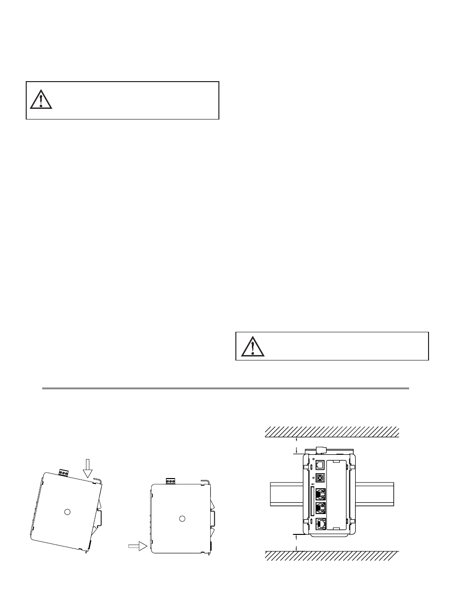
DIN rail should be mounted horizontally so that the unit’s ventilation holes
are vertical in relation to cabinet orientation. A minimum clearance of 1 inch
(25.4 mm) should be maintained above and below the unit in order to ensure
proper thermal regulation.
Figure 1 - Attach Fieldbus Gateway To DIN Rail
2
1
Immunity to Industrial Locations:
Electrostatic discharge
EN 61000-4-2 Criterion B
4 kV contact discharge
8 kV air discharge
Electromagnetic RF fields
EN 61000-4-3 Criterion A
10 V/m
Fast transients (burst)
EN 61000-4-4 Criterion A
power 2 kV
I/O signal 1 kV
Surge
EN 61000-4-5 Criterion B
signal
power
1kV
1kV L-L,2 kV L-G
RF conducted interference
EN 61000-4-6 Criterion A
3 V/rms
Emissions:
Emissions
EN 55011
Class A
ETHERNET
RS485
RS232
USB/PG
CF
RS232/PG
STS
1.00"
1.00"
min. clearance
min. clearance
TOP
BOTTOM
WARNING - DO NOT CONNECT OR DISCONNECT CABLES
WHILE POWER IS APPLIED UNLESS AREA IS KNOWN TO BE
NON-HAZARDOUS. USB PORT IS FOR SYSTEM SET-UP AND
DIAGNOSTICS AND IS NOT INTENDED FOR PERMANENT
CONNECTION.
WARNING - EXPLOSION HAZARD - DO NOT DISCONNECT
EQUIPMENT UNLESS POWER HAS BEEN SWITCHED OFF OR
AREA IS KNOWN TO BE NON-HAZARDOUS.