Led chart, Dip switch settings, Ports – B&B Electronics EIR-G-SFP-T - Quick Start Guide User Manual
Page 2
EIR-G-SFP-T 4612qsg
3
LED Chart
4
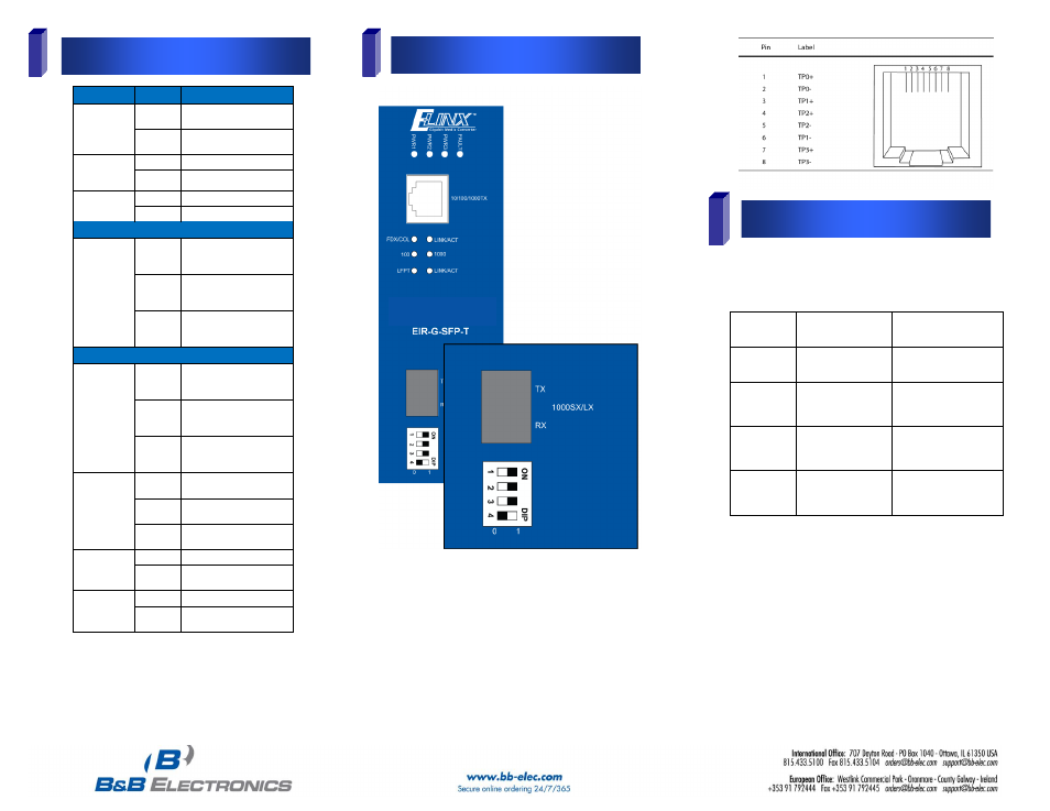
Ports
5
DIP Switch Settings
LEDs
State
Indication
FAULT
Steady
Power1, Power2, or
ports fail
Off
Power and ports
functioning normally
Power1
Power2
Power3
Steady
Power on
Off
Power off
LFPT
Steady
LFPT function enabled
Off
LFPT function disabled
1000Base-SX/LX
LINK/ACT
Steady
A valid network
connection established
for SFP port
Flashing Transmitting or receiving
data
ACT stands for Activity
Off
No valid network
connection established
for SFP port
10/100/1000Base-TX
LINK/ACT
Steady
A valid network
connection established
for copper port
Flashing Transmitting or receiving
data
ACT stands for Activity
Off
No valid network
connection established
for copper port
FDX/COL
Steady
Connected in full duplex
mode
Flashing Collision occurred
COL stands for Collision
Off
Connected in half duplex
mode
1000
Steady
Connected at 1000Mbps
Off
Not connected at
1000Mbps
100
Steady
Connected at 100Mbps
Off
Connected at 10Mbps
(100 & 1000 both Off)
The copper port is 10/100/1000Base-TX and will auto
negotiate a connection starting at gigabit speed.
High quality Category 5e cable or better should be used.
1000BASE-T requires all four pairs to be present and is far
less tolerant of poorly installed wiring than 100BASE-TX
systems. A 1000Base-SX/LX SFP module socket for Gigabit
optic expansion is located above DIP switch.
This device is plug_and_play; however, the following DIP
switch selections are available.
There are four pins on the DIP switch for port settings as
shown in the table below.
DIP Switch
No.
0 (OFF)
1 (ON)
1
Disable LFPT (default) Enable LFPT
2
Disable link down
alarm for copper port
(default)
Enable link down alarm for
copper port
3
Disable link down
alarm for SFP socket
port (default)
Enable link down alarm for
SFP socket port
Force Full Duplex
mode for SFP socket
port
Enable Duplex auto-
negotiation for SFP socket
port (default)
Link-Fault-Pass-Through (DIP Switch 1)
The default setting is link-fault-pass-through OFF. If not
enabled and one side of the link fails, the other side continues
transmitting packets, and waits for a response that never
comes. When ON, LFPT will force the link to shut down as
soon as it notices that the other link has failed. This gives the
application software a chance to react to the situation.
Link Down Alarm (DIP Switch 2 & 3) By default, the link
down alarms are disabled for both copper and fiber.
Duplex Mode (DIP Switch 4) The default setting is auto-
negotiation ON. You may force full duplex mode when set in
OFF position.