B&B Electronics 485TBLED - Datasheet User Manual
Page 2
485TBLED-0812-2/3
PR
O
D
U
C
T
INF
ORM
A
TIO
N
B
&
B
ELE
C
T
R
ON
ICS
www.bb-elec.com [email protected] [email protected]
International Office: 707 Dayton Road PO Box 1040 Ottawa, IL 61350 USA 815-433-5100 Fax 433-5104
European Office: Westlink Commercial Park Oranmore Co. Galway Ireland +353 91 792444 Fax +353 91 792445
The Echo jumper is used in the two-wire mode, and allows you to prevent data being sent from the RS-232 port from
being echoed back to the RS-232 port. Up to 32 receivers can be driven by any one RS-485 driver, allowing you to put
together large systems with many drop points. If you are using termination resistors, they should be located at opposite
ends of the system.
Proper operation of any RS-485 system requires the presence of a return path. The RS-485 Standard recommends that
a third wire be used for this. For safety, a 100 ohm resistor should be connected between Signal Ground and the
"reference wire" at every drop point. While it may be possible to interconnect Signal Grounds directly, this is not
recommended due to the danger of circulating currents possibly being present.
No wire type or maximum run length is listed in the RS-485 Standard. However, the RS-422 Standard (which is very
similar) recommends number 24AWG twisted pair telephone cable with a shunt capacitance of 16 picofarads per foot,
and no more than 4000 feet of distance.
Specifications:
Dimensions: 2.14” x 3.32” x .725” (54.5 x 84.34 x 18.43mm)
Supply Voltage: 9
– 14 Vdc
Temperature Range: 0° C
– 70° C
Data Rate: Up to 115.2 kbps
Connector: DB25 Female on RS-232 side
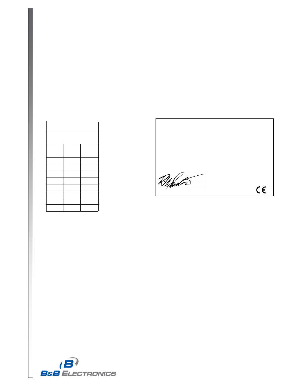
DECLARATION OF CONFORMITY
Ma
nufacturer’s Name:
B&B Electronics Manufacturing Company
Manufacturer’s Address:
P.O. Box 1040
707 Dayton Road
Ottawa, IL 61350 USA
Model Number:
485TBLED
Description:
RS-232 to RS-485 Converter
Type:
Light industrial ITE equipment
Application of Council Directive: 89/336/EEC
Standards:
EN 55022
EN 61000-6-1
EN 61000 (-4-2, -4-3, -4-4, -4-5, -4-6, -4-8, -4-11)
Robert M. Paratore, Director of Engineering
Table 1
Resistor Replacement For
Changing Baud Rate Timeouts
Baud
Rate
Time
(ms)
Resistor
R9/R14
(ohm)
1200
8.33
820K
2400
4.16
430K
4800
2.08
200K
9600
1.04
100K
19200
.520
56K
38400
.260
27K
57600
.176
16K
115200
.0868
8.2K