B&B Electronics 485OPB - Datasheet User Manual
Page 2
485OPB-1712-2/3
© 2004 by B&B Electronics. All rights reserved.
www.bb-elec.com [email protected] [email protected]
International Office: 707 Dayton Road PO Box 1040 Ottawa, IL 61350 USA 815-433-5100 Fax 433-5104
European Office: Westlink Commercial Park Oranmore Co. Galway Ireland +353 91 792444 Fax +353 91 792445
PR
O
D
U
C
T
INF
ORM
A
TIO
N
B
&
B
ELE
C
T
R
ON
ICS
FCC Approved Class A
Figure 4. PC Board Layout - Bottom
Figure 4. PC Board Layout - Top
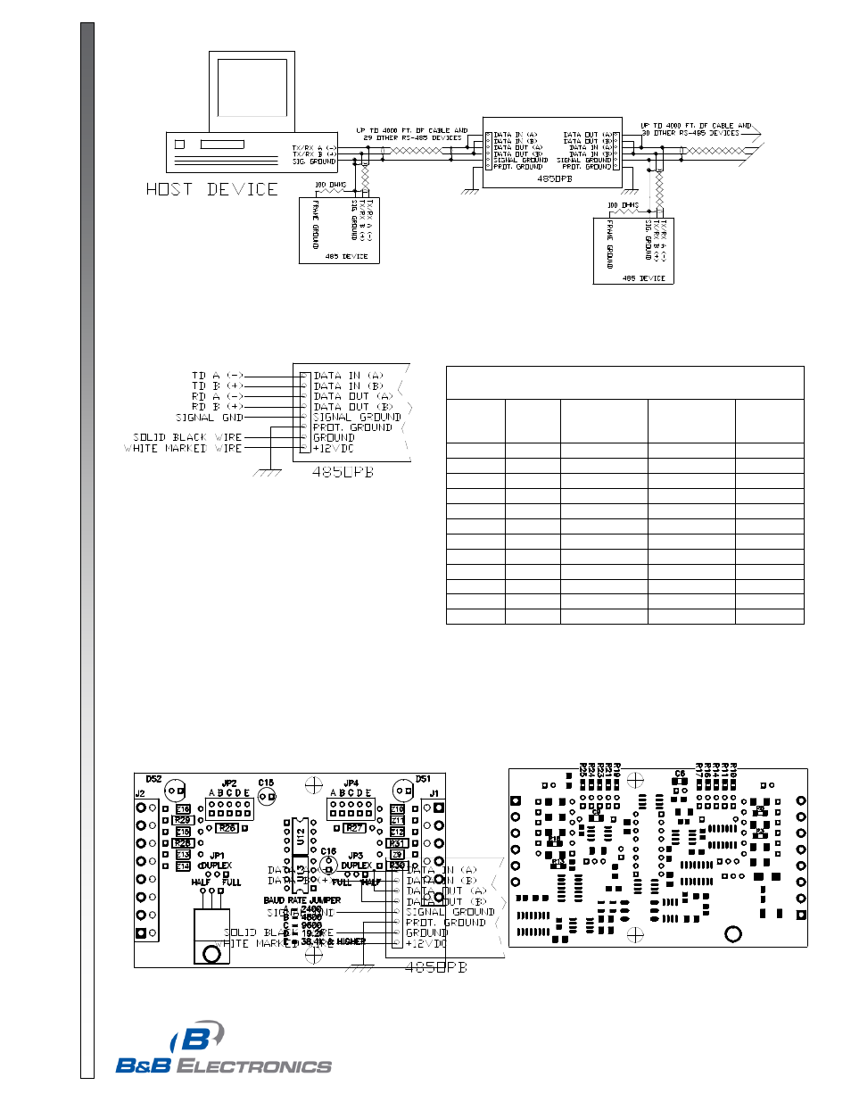
FIGURE 2. Four-Wire Setup
FIGURE 3. Two-Wire Setup
Table 1. Approximate Timeout Values
Baud
Rate
Time
(ms)
Resistors
R26 & R27
Capacitor
C15 & C16
(mfd)
Jumper
Position
J2 & J4
300
33.3
330K
0.1
E*1
600
16.6
160K
0.1
E*1
1200
8.33
820K
STD (0.01)
E*1
2400
4.16
STD (430K)
STD (0.01)
A
4800
2.08
STD (200K)
STD (0.01)
B
9600
1.04
STD (100K)
STD (0.01)
C
19.2K
0.52
STD (56K)
STD (0.01)
D
38.4 K
0.26
STD (27K)
STD (0.01)
E
57.6K
0.17
39K
STD (0.01)
E*2
115.2K
0.087
11K
STD (0.01)
E*2
230.4K
0.044
4.7K
STD (0.01)
E*2
460.8K
0.022
2.2K
STD (0.01)
E*2
Note: *1 Remove resistors R25 & R17 when installing R26 & R27,
remove C6 & C9 when installing C15 & C16 for 300 or 600 baud.
*2 Leave R25 & R17 in place when installing R26 & R27 values listed.
FIGURE 1. 485OPB As A Two-Wire Repeater