B&B Electronics 485OPDRI - Quick Start Guide User Manual
Quick start guide
Documentation Number – p/n 8455r002 485OPDRI-2212qsg
©2010 B&B Electronics Manufacturing Company
1
1
.
.
C
C
h
h
e
e
c
c
k
k
f
f
o
o
r
r
R
R
e
e
q
q
u
u
i
i
r
r
e
e
d
d
H
H
a
a
r
r
d
d
w
w
a
a
r
r
e
e
ILinx 485OPDRI Isolated Repeater
This Quick Start Guide
Additional Items Required but not included
o
A 10 to 48 VDC Power Supply.
o
RS-422/485 Cables.
2
2
.
.
I
I
n
n
f
f
o
o
r
r
m
m
a
a
t
t
i
i
o
o
n
n
–
–
U
U
L
L
C
C
l
l
a
a
s
s
s
s
1
1
D
D
i
i
v
v
2
2
1. Power, input /output (I/O) wiring must be in
accordance with Class 1 Division 2 wiring methods
[Article 501.10(B) of the National Electric code,
NFPA70] and in accordance with the local authority
having jurisdiction.
2. Maximum ambient air temperature 80°C
3. WARNING – EXPLOSION HAZARD:
SUBSTITUTION OF ANY COMPONENTS MAY
IMPAIR SUITABLITY FOR CLASS 1, DIVISION 2.
4. WARNING – EXPLOSION HAZARD: WHEN IN
HAZARDOUS LOCATIONS, TURNING OFF
POWER BEFORE REPLACING OR WIRING
MODULES
5. WARNING – EXPLOSION HAZARD: DO NOT
DISCONNECT EQUIPMENT UNLESS POWER HAS
BEEN SWITCHED OFF OR THE AREA IS KNOWN
TO BE NON-HAZARDOUS.
6.
WARNING – THIS APPARATUS IS SUITABLE FOR
USE IN CLASS 1 DIVISION 2, GROUPS A, B, C,
AND D, OR UNCLASSIFIED AREAS
.
Quick Start Guide
ILinx 485OPDRI
Triple Isolated RS-422/485
Repeater
3
3
.
.
I
I
n
n
f
f
o
o
r
r
m
m
a
a
t
t
i
i
o
o
n
n
–
–
F
F
r
r
o
o
n
n
t
t
P
P
a
a
n
n
e
e
l
l
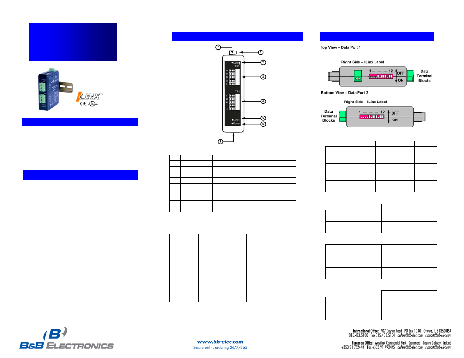
Front Panel
1
Power TB
2 Position, Removable
2
DATA LED
Red, Flashes when RS-422/485
Data Received on TB1
3
TB 1
5 Position, Removable
4
TB 2
5 Position, Removable
5
DATA LED
Red Flashes when RS-422/485
Data Transmitted on TB2
6
Power LED
Red, ON When Power Applied
7
Dip Switch
12 Position, One on the top of the
Unit, on the bottom of the unit
RS-422/485 Terminal Blocks
TB1
RS-485 2-Wire
RS-422/485 4-Wire
A
GND
GND
B
Data B(+)
RDB(+)
C
Data A(-)
RDA(-)
D
---
TDB(+)
E
---
TDA(-)
TB2
RS-485 2-Wire
RS-422/485 4-Wire
F
GND
GND
G
Data B(+)
RDB(+)
H
Data A(-)
RDA(-)
I
---
TDB(+)
J
---
TDA(-)
4
4
.
.
I
I
n
n
f
f
o
o
r
r
m
m
a
a
t
t
i
i
o
o
n
n
-
-
D
D
I
I
P
P
S
S
w
w
i
i
t
t
c
c
h
h
Communications
Mode
1
2
3
4
RS-485
ON
ON
ON
ON
2-Wire
Half Duplex
RS-485
ON
OFF
OFF
OFF
4-Wire
Full Duplex
RS-422
OFF
OFF
OFF
OFF
Full Duplex
Termination Resistor
5
Use the 120Ω
ON
Built in Termination
Use External
OFF
or no termination
Transmit Bias
6
Use the 1.2KΩ
Transmit
OFF
Bias Resistor
Use External or no
ON
Transmit Bias Resistor
Receive Bias
7
Use the 1.2KΩ Receive
OFF
Bias Resistor
Use External or no
ON
Transmit Bias Resistor