B&B Electronics SCP311T-DFTB3 - Quick Start Guide User Manual
Page 2
Document Number – pn 9027 SCPx11-0712R002qsg
©2011 B&B Electronics Manufacturing Company
5
5
.
.
P
P
o
o
w
w
e
e
r
r
C
C
o
o
n
n
n
n
e
e
c
c
t
t
i
i
o
o
n
n
1. Connect your external power supply to the two position
power terminal block (A). The polarity is indicated on the
front label. The converter will accept 10 to 30 VDC, 2.5W
Maximum.
2. The terminal block will accept 28 to 12 AWG Wire.
6
6
.
.
W
W
i
i
r
r
i
i
n
n
g
g
E
E
x
x
a
a
m
m
p
p
l
l
e
e
s
s
R
R
S
S
-
-
4
4
8
8
5
5
2
2
-
-
W
W
i
i
r
r
e
e
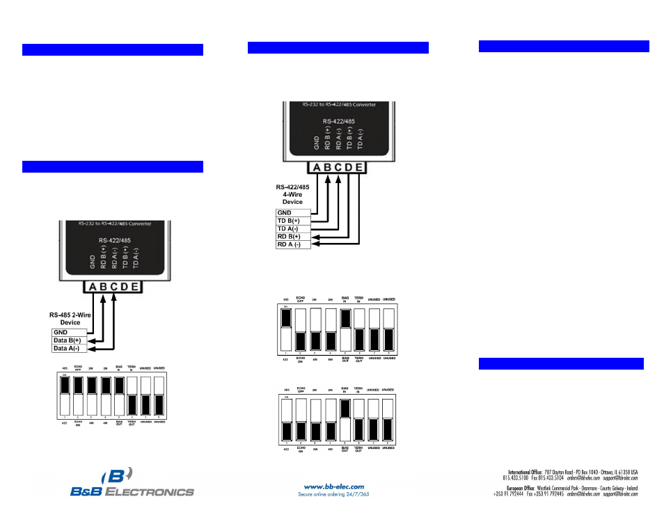
RS-485 2-Wire
1. In this example, the converter is set up to use internal
bias and no termination.
(NOTE: This is the default shipping configuration)
8
8
.
.
B
B
i
i
a
a
s
s
&
&
T
T
e
e
r
r
m
m
i
i
n
n
a
a
t
t
i
i
o
o
n
n
1.
The circuit can be biased using the built in 1 kΩ pull-
up and pull-down resistors. This is controlled with DIP
switch position 5. The default setting is ON (bias
resistors “in.”)
a. When an RS-485 network is in an idle state, all
nodes are in listen (receive) mode. Under this
condition there are no active drivers on the
network. All drivers are tri-stated. Without
anything driving the network, the state of the line
is unknown. If the voltage level at the receiver's A
and B inputs is less than ±200mV the logic level at
the output of the receivers will be the value of the
last bit received. In order to maintain the proper
idle voltage state, bias resistors must be applied
to force the data lines to the idle condition.
2. If Termination is necessary on the receive lines, a
built in 120 Ω resistor can be switched in using DIP
Switch Position 6. In most cases, termination is not
required. The default setting is OFF (termination
“out”.)
a. Termination is used to match impedance of a
node to the impedance of the transmission line
being used. Termination increases load on the
drivers, increases installation complexity, changes
biasing requirements and makes system
modification more difficult. Generally, termination
should only be used for long distances. “If in
doubt, leav
e it out.”
7
7
.
.
W
W
i
i
r
r
i
i
n
n
g
g
E
E
x
x
a
a
m
m
p
p
l
l
e
e
s
s
R
R
S
S
-
-
4
4
2
2
2
2
/
/
4
4
8
8
5
5
4
4
-
-
W
W
i
i
r
r
e
e
RS-422/485 4-Wire
1. In this example, the converter is set up to use internal
bias and no termination.
RS-485 4-Wire DIP Switch
RS-422 4-Wire DIP Switch
9
9
.
.
L
L
o
o
o
o
p
p
B
B
a
a
c
c
k
k
T
T
e
e
s
s
t
t
/
/
T
T
r
r
o
o
u
u
b
b
l
l
e
e
s
s
h
h
o
o
o
o
t
t
i
i
n
n
g
g
Configure for RS-485 Four wire
Jumper terminals B to D and C to E
Connect a PC to the RS-232 port
TD and RD LED’s are ON when power is applied.
Using hyper terminal or similar program, connect to
the appropriate COM port. Turn off hyper terminal
local echo
Transmit data. The same data should be returned.
When data is sent and looped back, the TD and
RD LED’s blink on and off indicating data flow