B&B Electronics 232USB9M-LS - Quick Start Guide User Manual
Usb connector serial connector, Product overview
1
Install the Drivers
2
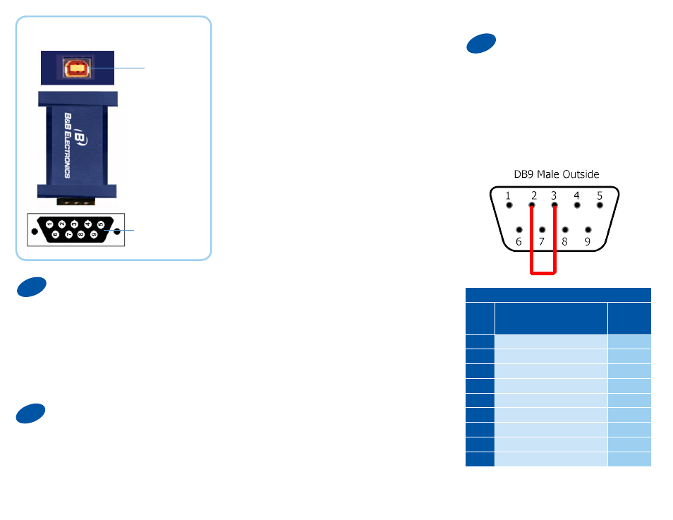
RS-232 Pinout (DB9 Male DTE)
PIN
Signal Name
RS-232
Signals
1
DCD (Data Carrier Detect)
Input
2
RD (Receive Data)
Input
3
TD (Transmit Data)
Output
4
DTR (DTE Ready)
Output
5
SG (Signal Ground)
Ground
6
DSR (DCE Ready)
Input
7
RTS (Request to Send)
Output
8
CTS (Clear to Send)
Input
9
RI (Ring Indicator)
Input
Product Overview
USB
Connector
Serial
Connector
Warning: To prevent installation
errors, do not plug in the hardware
until you have already installed the
drivers.
Use the included CD to install
the converter’s drivers.
Connect the converter’s USB port
to a USB port on your computer or
USB hub.
Connect the Converter
When the installation is complete the
converter will appear in Windows
Device Manager as an additional
COM port.
Most of the time a DB9 male will
be a DTE. A DB9 female will
usually be a DCE.
A DTE device is “Data Terminal
Equipment.” This includes computers,
PLCs, and most devices that are not
used to extend communications.
(Think “COMPUTER” for DTE.)
A DCE device is “Data Communications
Equipment.” This includes modems and
other devices that extend communica-
tions, like RS-422, RS-485, fiber optic
converters or radio modems.
(Think “MODEM” for DCE.)
If both devices have a DB9 male
you will need a crossover cable.
If both devices are DB9 female
you will need a crossover cable.
When one device is female and
one device is male, use a
straight-through cable.
3
Loopback Test
Loopback pins 2 and 3. Using Hyper
Terminal or similar program, connect
to the COM port. Set the desired baud
rate. Ensure that Hyper Terminal local
echo is OFF. Transmit data. If the
same character string is returned, the
test is good.