B&B Electronics 232TTL - Datasheet User Manual
Port powered ttl/rs-232 converters
www
.
bb
-
elec
.
com
|
port powered ttL/rS-232 Converters
232TTL, 232OTTL
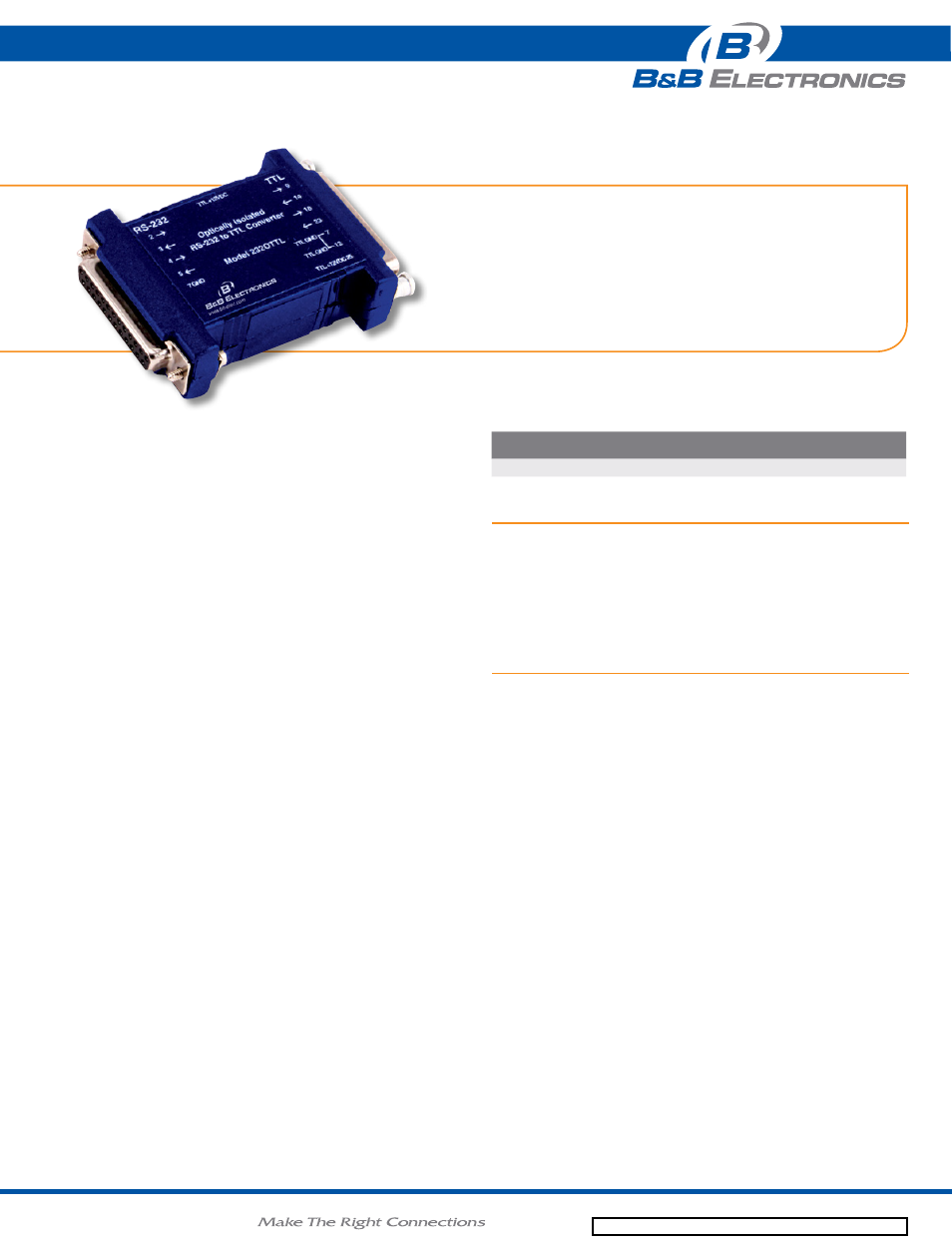
Models 232TTL and 232OTTL convert RS-232 signals to 0-5 VDC TTL
levels. The 232OTTL provides 1500V optical isolation. Two channels are
used to convert from RS-232 to TTL signals and two channels are used to
convert fomr TTL signals to RS-232.
These converters support RD, TD, RTS, and CTS. The DB25P male
connector (DCE) is for the RS-232 side. The DB25S female connector is
for the TTL side. The 232TTL supports baud rates up to 115K baud, the
232OTTL supports up to 38.4K baud.
It is important that only TTL logic (0 to +5V) is used for the TTL side of the
converter. The maximum sinking current for one TTL output is 8 mA. The
maximum source current for one TTL is 0.8 mA. Signal levels are inverted
by the converter in its standard configuration as shown in Table 1.
• Convert 2 channels in each direction from TTL to RS-232
• Baud rates up to 115.2 kbps (38.4 kbps on isolated model)
• Powered from RS-232 data/handshake lines - no power
supply required
• Optically isolated version (Model 232OTTL)
proDuCt FeatureS
aCCeSSorieS
232PS - 12VDC@100mA wall transformer power supply, 2.5mm plug
E1250BL-BB3 - 220-240 VAC to 12 VDC wall power supply, 2.5mm plug
Euro CEE7/7 plug
232CAMS - DB25 male to DB9 female adapter cable, 15.24 cm/6 in
232SGF - 25-pin gender reverser - changes male port to female
orDering inFormation
Model
nuMber
rs-232
ConneCtor
ttl ConneCtor
ttl vdC
isolation
232TTL
DB25 Male
DB25 Female
5V
232OTTL
DB25 Female
DB25 Male
5V
1500V
The 232OTTL has the option for non-inverted outputs. See table 2,
"Operations Requiring Modification" if non-inverted outputs are desired.
Power
The 232TTL requires an external +12VDC power supply connected either
through 2.5mm jack or pins 12(GND) and 25 (+12VDC) on the TTL side.
The 232OTTL requires both Port Power on the RS-232 side, and external
+12VDC power supply connected either through 2.5mm jack or pins
12(GND) and 25 (+12VDC) on the TTL side.
Port power is derived from the outputs of the host RS-232 port. TD, RTS,
and DTR lines may be used to port power the RS-232 side. A minimum
of two of these lines in either high or low states is required for proper
operation. To externally power the RS-232 side, connect the positive lead
of the +12VDC power supply to pin 25 and the GND lead to pin 12 of the
DB25 female connector.
ttl input
rs-232 output
high (>2.0V)
-5 V maximum, -9V typical
low (<0.8V)
+5 V minimum, +9V typical
ttl output rs-232 input
high (>2.0V)
-5 V maximum, -9V typical
low (<0.8V)
+5 V minimum, +9V typical
table 1: standard inverted outputs
options requiring Modification
The 232OTTL may be modified to non-inverted signals as shown in Table
2 by placing a jumper wire across JP1:A labeled "NI"
The 232OTTL may also be modified to accept a +5V supply on the TTL
side. Remove the 0 ohm surface mount resister labeled R13 and place a
jumper wire across JP1:B labeled +5V. A +4.75 to +5.25V at a maximum
of 25mA is necessary to power the TTL side of the converter when this
modification is made.
ttl input
rs-232 output
high (>2.0V)
-5 V maximum, -9V typical
low (<0.8V)
+5 V minimum, +9V typical
ttl output rs-232 input
high (>2.0V)
-5 V maximum, -9V typical
low (<0.8V)
+5 V minimum, +9V typical
table 2: Modified to non-inverted outputs
232TTL, 232OTTL_3713ds