B&B Electronics SDR-480 Series - Datasheet User Manual
Sdr-480, Series, Specification
SPECIFICATION
MODEL
DC VOLTAGE
RATED CURRENT
CURRENT RANGE
RATED POWER
PEAK CURRENT
PEAK POWER
Note.6
OUTPUT
VOLTAGE ADJ. RANGE
LINE REGULATION
LOAD REGULATION
SETUP, RISE TIME
HOLD UP TIME (Typ.)
VOLTAGE RANGE
Note.7
FREQUENCY RANGE
EFFICIENCY (Typ.)
INPUT
INRUSH CURRENT (Typ.)
LEAKAGE CURRENT
OVER TEMPERATURE
SAFETY STANDARDS
HARMONIC CURRENT
EMS IMMUNITY
WORKING TEMP.
Note.5
WORKING HUMIDITY
STORAGE TEMP., HUMIDITY
DC OK REALY CONTACT RATINGS (max.)
TEMP. COEFFICIENT
VIBRATION
MTBF
DIMENSION
OTHERS
NOTE
PACKING
OVERLOAD
OVER VOLTAGE
AC CURRENT (Typ.)
1500ms, 150ms/230VAC
3000ms, 150ms/115VAC at full load
14ms/230VAC at full load
90 ~ 264VAC
127 ~ 370VDC
47 ~ 63Hz
94%
0.94/230VAC
0.99/115VAC at full load
5A/115VAC
2.5A/230VAC
56 ~ 65V
40A/115VAC
80A/230VAC
<0.8mA / 240VAC
29 ~ 33V
Protection type : Shut down o/p voltage with auto-recovery or re-power on to recovery
105
5
(TSW : detect on heatsink of power switch)
Protection type : Shut down o/p voltage, recovers automatically after temperature goes down
UL508 TUV EN60950-1 approved
,
Compliance to EN55022 (CISPR22) Class B
Compliance to EN61000-3-2,-3
-25 ~ +70
(Refer to output load derating curve)
60Vdc/0.3A, 30Vdc/1A, 30Vac/0.5A resistive load
20 ~ 95% RH non-condensing
-40 ~ +85
, 10 ~ 95% RH
0.03%/
(0 ~ 50
Component:10 ~ 500Hz, 2G 10min./1cycle, 60min. each along X, Y, Z axes; Mounting: Compliance to IEC60068-2-6
112.9Khrs min.
MIL-HDBK-217F (25
)
Compliance to EN61000-4-2,3,4,5,6,8,11, ENV50204, EN55024, EN61000-6-2 (EN50082-2), EN61204-3, heavy industry level,
criteria A , SEMI F47 approved
85.5*125.2*128.5mm (W*H*D)
1.6Kg; 8pcs/13.8Kg/0.9CUFT
POWER FACTOR (Typ.)
SDR-480-48
48V
10A
0 ~ 10A
480W
15A
120mVp-p
48 ~ 55V
1.0%
0.5%
1.0%
SDR-480-24
24V
20A
0 ~ 20A
480W
30A
720W (3sec.)
100mVp-p
24 ~ 28V
1.2%
0.5%
1.0%
Features :
SDR-480
series
WITHSTAND VOLTAGE
ISOLATION RESISTANCE
I/P-O/P:3KVAC
I/P-FG:1.5KVAC
O/P-FG:0.5KVAC
O/P-DC OK:0.5KVAC
I/P-O/P, I/P-FG, O/P-FG:>100M Ohms / 500VDC / 25
/ 70% RH
EMI CONDUCTION & RADIATION
ENVIRONMENT
SAFETY &
FUNCTION
EMC
(Note 4)
PROTECTION
RIPPLE & NOISE (max.)
Note.2
VOLTAGE TOLERANCE
Note.3
1. All parameters NOT specially mentioned are measured at 230VAC input, rated load and 25
of ambient temperature.
2. Ripple & noise are measured at 20MHz of bandwidth by using a 12" twisted pair-wire terminated with a 0.1uf & 47uf parallel capacitor.
3. Tolerance : includes set up tolerance, line regulation and load regulation.
4. The power supply is considered a component which will be installed into a final equipment. The final equipment must be re-confirmed that it still meets
EMC directives.
5. Installation clearances : 40mm on top, 20mm on the bottom, 5mm on the left and right side are recommended when loaded permanently with full power.
In case the adjacent device is a heat source, 15mm clearance is recommended.
6. 3 seconds peak power max. and the average output power should not exceed the rate power.
7. Derating may be needed under low input voltage. Please check the derating curve for more details.
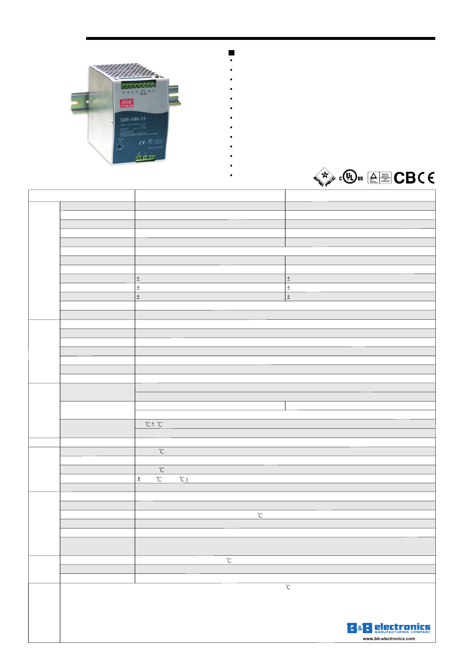
480W Single Output Industrial DIN RAIL with PFC Function
High efficiency 94% and low power dissipation
150% peak load capability
Built-in active PFC function, PF>0.94
Protections: Short circuit / Overload / Over voltage / Over temperature
Cooling by free air convection
Built-in constant current limiting circuit
Can be installed on DIN rail TS-35/7.5 or 15
UL 508(industrial control equipment)approved
EN61000-6-2(EN50082-2) industrial immunity level
100% full load burn-in test
3 years warranty
Built-in DC OK relay contact
150% peak load capability
File Name:SDR-480-SPEC 2009-04-22
Normally w
more than 3
and then shut down o/p voltage with auto-recovery
orks within 110 ~ 150% rated output power for
seconds
>150% rated power, constant current limiting with auto-recovery within 2 seconds and may cause to shut down if over 2 seconds
PQ
S
E
M
I F
4
7