Usoptl4dr-x – B&B Electronics USOPTL4DR-LS - Datasheet User Manual
Page 2
International Office: 707 Dayton Road PO Box 1040 Ottawa, IL 61350 USA 815-433-5100 Fax 433-5104
European Office: Westlink Commercial Park Oranmore Co. Galway Ireland +353 91 792444 Fax +353 91 792445
isolated usB/rs-422/485 Converters
USOPTL4DR-x
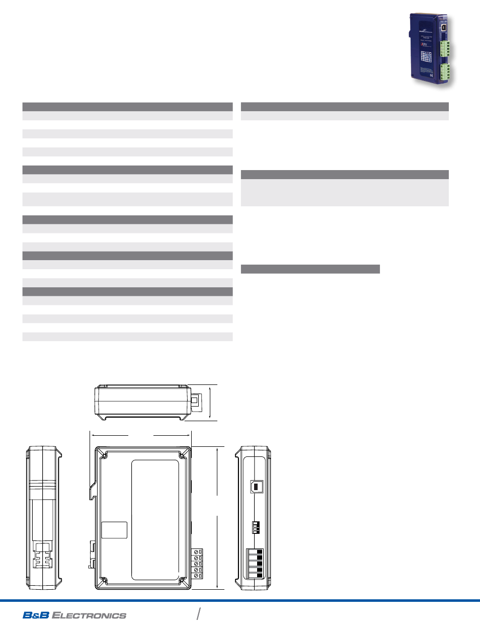
meCHaniCal diagram
sPeCiFiCations
Serial teChnology
RS-485 2-Wire
Data A(-), Data B(+), Ground
RS-485 4-Wire
TDA(-), TDB(+), RDA(-), RDB(+), Ground
Connector
Removable terminal block, 12 to 28 AWG
Data Rate
Up to 921.6 Kbps
Isolation
3000 V optical isolation
Surge Protection
15 KV ESD
uSB teChnology
USB Compatibility
2.0 (backward compatible)
USB Data Rate
12 Mbps
Connector
Type B female, high retention
(15 Newtons / 3.4 lbs-force withdrawal)
Driver CD
Windows 2000, XP, Vista, 7 (32/64 bit), 8 (32/64 bit)
Power
Source
USB port
Input Voltage
5 VDC
Consumption
~2.5 W (high power device, draws >500 mA
MeChaniCal
Dimensions
9.7 x 11.9 x 3.1 cm (3.8 x 4.7 x 1.2 in)
Enclosure
DIN rail mountable, plastic
Weight
222.3 g (0.49 lbs) with USB cable
enVironMental
Operating Temperature
0 to 70°C (32 to 158°F)
Storage Temperature
-40 to 85°C (-40 to 185°F)
Operating Humidity
0 to 95% Non-condensing
MTBF USOPTL4DR
184,556 hours
MTBF USOPTL4DR-2
79,551 hours
MTBF Calc. Method
Parts Count Reliability Prediction
aPProValS / CertiFiCationS
Emissions FCC Class B, CISPR Class B (EN55022:2006)
CE
EN 61000-6-1: 2007 Generic Standards for Residential, Commercial
and Light-Industrial Environments
EN 61000-4-2: 2009 Electro-Static Discharge (ESD)
EN 61000-4-3: 2006 +A1 +A2 +IS1 Radiated Field Immunity (RFI)
EN 61000-4-4: 2012 Electrical Fast Transients-Burst Immunity (EFT)
EN 61000-4-6: 2009 Conducted Immunity
inForMation – FCC ruleS
This device complies with Part 15 of the FCC rules. Operation is subject to the
following two conditions:
(1) This device may not cause harmful interference.
(2) This device must accept any interference that may cause undesired operation.
1
2
3
4
ON
9.7 cm
3.8 in
11.9 cm
4.7 in
3.1 cm
1.2 in
tB PoSition
laBel
FunCtion
A
T-
TDA(-)
B
T+
TDB(+)
C
R-
RDA(-)
D
R+
RDA(+)
E
G
Ground
terminal BloCk
The terminal block layout is top to bottom (as viewed
from a DIN rail installation). The signal names on the front
label are only visible when the terminal block is removed.
The USOPTL4DR-2 has two terminal blocks. In both
configurations, the TB layout is the same.