Pin description – Rainbow Electronics MAX1495 User Manual
Page 7
MAX1491/MAX1493/MAX1495
3.5- and 4.5-Digit, Single-Chip
ADCs with LCD Drivers
_______________________________________________________________________________________
7
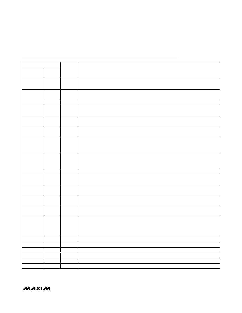
Pin Description
PIN
MAX1491
MAX1493
MAX1495
NAME
FUNCTION
1
30
INTREF
Internal Reference Logic Input. Connect to GND to select external reference mode. Connect
to DV
DD
to select the internal reference mode.
2
31
DV
DD
Digital Power Input. Connect DV
DD
to a 2.7V to 5.25V power supply. Bypass DV
DD
to GND
with a 0.1µF and a 4.7µF capacitor.
3
32
GND
Ground
4
1
AV
DD
Analog Power Input. Connect AV
DD
to a 2.7V to 5.25V power supply. Bypass AV
DD
to GND
with a 0.1µF and a 4.7µF capacitor.
5
2
AIN+
Positive Analog Input. Positive side of fully differential analog input. Bypass A
IN+
to GND with
a 0.1µF or greater capacitor.
6
3
AIN-
Negative Analog Input. Negative side of fully differential analog input. Bypass A
IN-
to GND
with a 0.1µF or greater capacitor.
7
4
REF-
Negative Reference Input. For internal reference operation, connect REF- to GND. For
external reference operation, bypass REF- to GND with a 0.1µF capacitor and set V
REF-
from
-2.2V to +2.2V, provided V
REF+
> V
REF-
.
8
5
REF+
Positive Reference Input. For internal reference operation, connect a 4.7µF capacitor from
REF+ to GND. For external reference operation, bypass REF+ to GND with a 0.1µF capacitor
and set V
REF+
from -2.2V to +2.2V, provided V
REF+
> V
REF-
.
9
6
LOWBATT Low Batter y Inp ut. W hen V
LOWB ATT
< 2.048V ( typ ) , the LO WBATT sym b ol on the LC D tur ns on.
10
7
RANGE
Range Logic Input. RANGE controls the fully differential analog input range. Connect to GND
for the ±2V input range. Connect to DV
DD
for the ±200mV input range.
11
8
DPSET1
Decimal Point Logic Input 1. Controls the decimal point of the LCD. See the Decimal Point
Control section.
12
9
DPSET2
Decimal Point Logic Input 2. Controls the decimal point of the LCD. See the Decimal Point
Control section.
13
10
PEAK
Peak Logic Input. Connect to DV
DD
to display the highest ADC value on the LCD. Connect to
GND to disable the peak function.
14
11
HOLD
Hold Logic Input. Connect to DV
DD
to hold the current ADC value on the LCD. Connect to
GND to update the LCD at a rate of 2.5Hz and disable the hold function. For the MAX1495,
placing the device into hold mode initiates an enhanced offset calibration. Assert HOLD high
for a minimum of 2s to ensure the completion of enhanced offset calibration.
15
12
SEG1
LCD Segment 1 Driver
16
13
SEG2
LCD Segment 2 Driver
17
14
SEG3
LCD Segment 3 Driver
18
15
SEG4
LCD Segment 4 Driver
19
16
SEG5
LCD Segment 5 Driver
20
17
SEG6
LCD Segment 6 Driver