Electrical characteristics (continued) – Rainbow Electronics MAX1495 User Manual
Page 4
MAX1491/MAX1493/MAX1495
3.5- and 4.5-Digit, Single-Chip
ADCs with LCD Drivers
4
_______________________________________________________________________________________
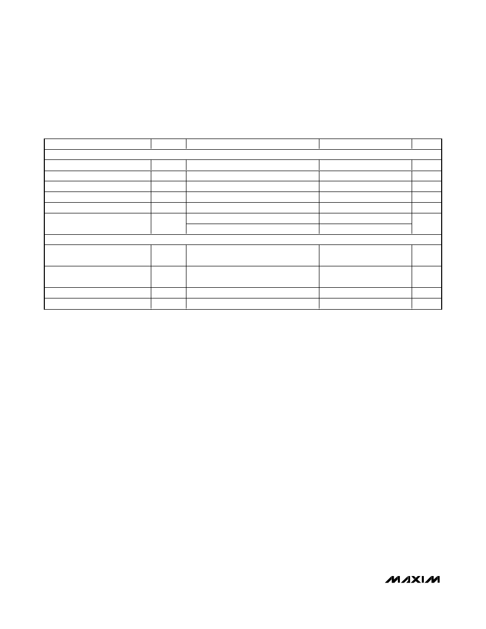
ELECTRICAL CHARACTERISTICS (continued)
(AV
DD
= DV
DD
= +2.7V to +5.25V, GND = 0, V
REF+
- V
REF-
= 2.048V (external reference), C
NEG
= 0.1µF. All specifications are T
MIN
to T
MAX
, unless otherwise noted. Typical values are at +25°C, unless otherwise noted.)
PARAMETER
SYMBOL
CONDITIONS
MIN
TYP
MAX
UNITS
POWER SUPPLY
AV
DD
Voltage
AV
DD
2.70
5.25
V
DV
DD
Voltage
DV
DD
2.70
5.25
V
Power-Supply Rejection AV
DD
PSRR
A
(Note 7)
80
dB
Power-Supply Rejection DV
DD
PSRR
D
(Note 7)
100
dB
AV
DD
Current
I
AVDD
(Note 8)
660
µA
DV
DD
= 5V
320
DV
DD
Current
I
DVDD
DV
DD
= 3.3V
180
µA
LCD DRIVER
RMS Segment-On Voltage
1.92 x
DV
DD
V
RMS Segment-Off Voltage
1 / 3 x
DV
DD
V
Display Multiplex Rate
107
Hz
LCD Data-Update Rate
2.5
Hz
Note 1: Integral nonlinearity is the derivation of the analog values at any code from its theoretical value after nulling the gain error
and offset error.
Note 2: Offset calibrated.
Note 3: Offset nulled.
Note 4: The input voltage range for the analog inputs is given with respect to the voltage on the negative input of the differential pair.
Note 5: For the range of V
AIN+
or V
AIN-
= -2.2V to +2.2V and V
REF+
or V
REF-
= -2.2V to +2.2V.
Note 6: External load must be constant during conversion for specified accuracy. Guaranteed specification of 2mV/mA is a result of
production test limitations.
Note 7: Measured at DC by changing the power-supply voltage from 2.7V to 5.25V and measuring its effect on the conversion error.
PSRR at 50Hz and 60Hz exceeds 120dB with filter notches of 10, 20, 30, 40, 50, or 60Hz.
Note 8: Analog power-supply currents are measured with all digital inputs at either GND or DV
DD
. Digital power-supply currents
measured with all digital inputs at either GND or DV
DD
.