Typical operating circuit – Rainbow Electronics MAX1495 User Manual
Page 21
MAX1491/MAX1493/MAX1495
3.5- and 4.5-Digit, Single-Chip
ADCs with LCD Drivers
______________________________________________________________________________________
21
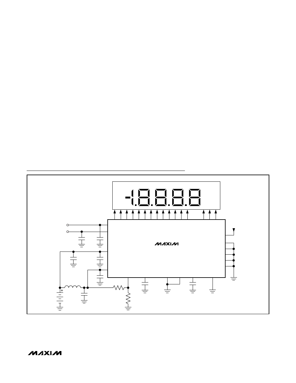
Typical Operating Circuit
MAX1493
MAX1495
(MAX1491)
0.1
µF
4.7
µF
0.1
µF
0.1
µF
0.1
µF
4.7
µF
4.7
µF
10
µF
L
ISO
R
HI
R
LOW
2.7V TO
5.25V
AIN+
AIN-
DV
DD
AV
DD
LOWBATT
V
NEG
GND
REF-
REF+
RANGE
INTREF
DV
DD
PEAK
DPON
DPSET1
HOLD
DPSET2
BACKPLANE
CONNECTIONS
SEG1–SEG13
(SEG1–SEG10)
HOLD
PEAK
LOW BATTERY
V
IN
Gain Error
Gain error is the amount of deviation between the mea-
sured full-scale transition point and the ideal full-scale
transition point.
Common-Mode Rejection
Common-mode rejection is the ability of a device to
reject a signal that is common to both input terminals.
The common-mode signal can be either an AC or a DC
signal or a combination of the two. CMR is often
expressed in decibels.
Normal-Mode 50Hz and 60Hz Rejection
(Simultaneously)
Normal mode rejection is a measure of how much output
changes when 50Hz and 60Hz signals are injected into
just one of the differential inputs. The MAX1491/
MAX1493/MAX1495 sigma-delta converter uses its inter-
nal digital filter to provide normal mode rejection to both
50Hz and 60Hz power-line frequencies simultaneously.
Power-Supply Rejection Ratio
Power-supply rejection ratio (PSRR) is the ratio of the
input supply change (in volts) to the change in the con-
verter output (in volts). It is measured typically
in decibels.
Enhanced Offset Calibration
Enhanced offset calibration is a more accurate calibra-
tion method that is needed in the case of the ±200mV
range and 4.5-digit resolution. The MAX1493/MAX1495
perform the enhanced offset calibration upon power-up.
The MAX1495 also performs enhanced offset calibration
on demand with the HOLD input.