Wide brightness range ccfl backlight controllers – Rainbow Electronics MAX1839 User Manual
Page 19
MAX1739/MAX1839
†
Wide Brightness Range
CCFL Backlight Controllers
______________________________________________________________________________________
19
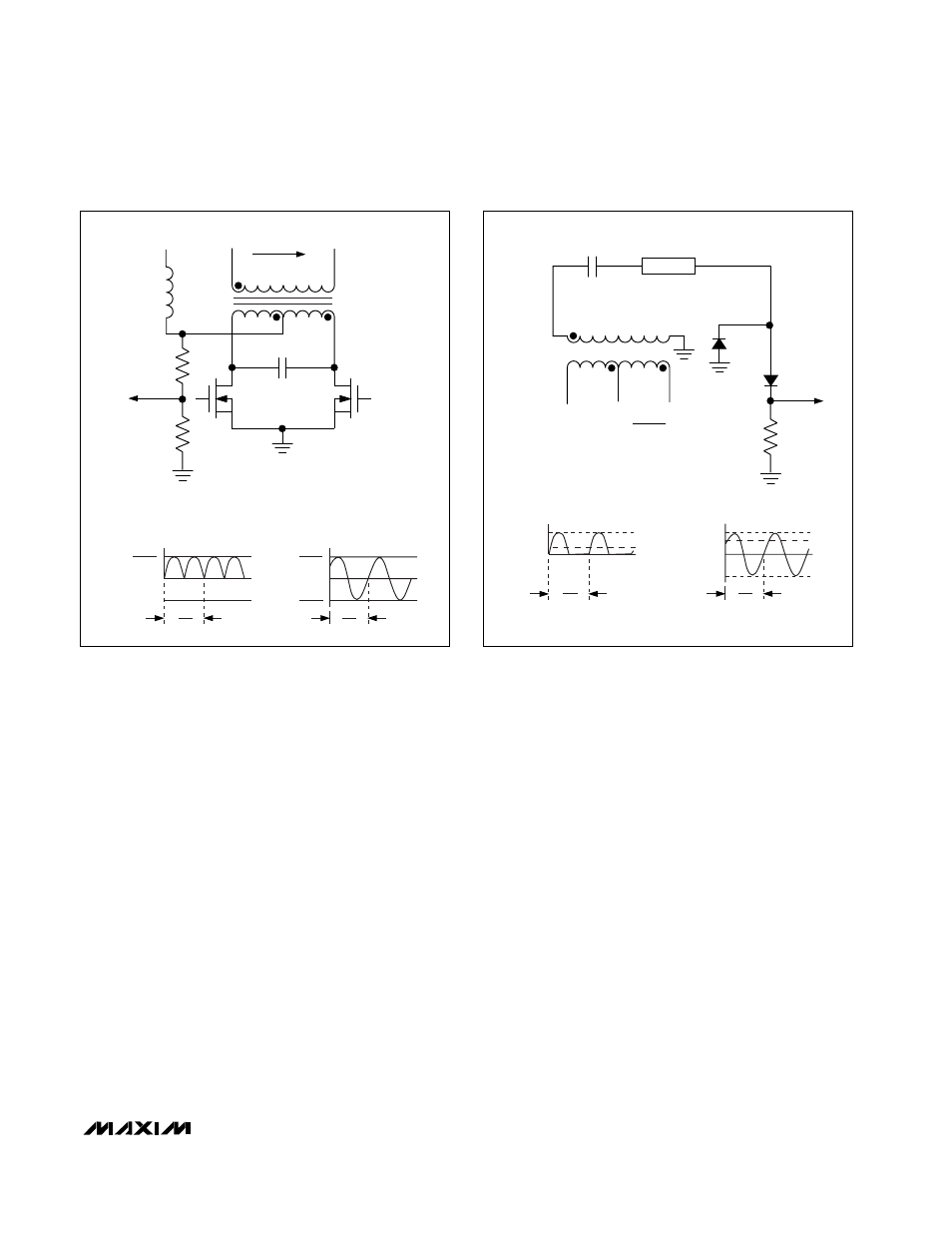
The MAX1739/MAX1839 regulate the average current
through the CCFL. The current is sensed through the
sense resistor (R13) at CSAV. The voltage at CSAV is
the half-wave rectified representation of the current
through the lamp (Figure 10). The MAX1739/MAX1839
regulate the average voltage at CSAV (I
R13, AVG
✕
R13)
and are controlled by either the analog interface or the
SMBus interface. To set the maximum lamp current,
determine R13 as follows:
R13 = 0.4304 / I
L,RMS,MAX
where I
L,RMS,MAX
is the maximum RMS lamp current.
MINDAC and the wave shape influence the actual max-
imum RMS lamp current. Use an RMS current meter to
make final adjustments to R13.
Loop Compensation
C
CCI
sets the speed of the current control loop that is
used during startup, maintaining lamp current regula-
tion, and during transients caused by changing the
lamp current setting. The standard C
CCI
value is
0.01µF. Larger values limit lamp current overshoot.
Smaller values speed up its response to changes in the
lamp current setting, but can lead to instability for
extremely small values. Very large values of C
CCI
increase the delay to strike voltage in DPWM and can
cause loss of regulation in the extreme case. Note that
very large C
CCV
can do the same thing.
C
6
not only affects loop compensation, but it also affects
the waveform shape, overall efficiency, and the maxi-
mum necessary secondary transformer voltage. Low val-
ues of C
6
improve loop stability, especially in systems
using a CCFL with a large difference between its restrike
voltage and its operating voltage (characteristic of long
narrow CCFLs) during DPWM. A low value of C
6
also
improves stability when the lamp’s operating voltage
drops with an increase in lamp current. However, low
values of C
6
increase the maximum necessary trans-
former voltage. C
7
interacts with C
6
and affects the
Royer frequency, Royer Q value, and overall efficiency.
C
CCV
sets the speed of the voltage control loop that
affects DPWM transients and operation in fault condi-
tions. If DPWM is not used, the voltage control loop
should only be active during fault conditions. The stan-
dard value of C
CCV
is 3300pF. Use the smallest value
of C
CCV
necessary to set an acceptable fault transient
response and not cause excessive ringing at the begin-
ning of a DPWM pulse. Note that the worst-case fault
R4
TO
CTFB
R5
T1
V
CT
L1
N
P
N
P
N
S
V
S
= V
S(RMS)
= N
✕
1.1
✕
VCT
N = N
S
/N
P
N2B
N2A
2
π
ω
N
πV
CT
2
T1 SECONDARY
VOLTAGE (PIN 10–PIN 6)
-N
πV
CT
2
2
π
ω
πV
CT
2
T1 PRIMARY-TAP
VOLTAGE (PIN 2)
V
CT
is the average DC voltage at center top
D5A
D5B
CSAV
R13
T1
C6
CCFL
2
π
ω
I
L,PK
I
L,RMS
-I
L,PK
I
LAMP
I
L,PK
I
R13, AVG
2
π
ω
I
R13
I
L, RMS, MAX
= 0.04304
R13
Figure 9. Transformer Primary/Secondary Voltage Relationship
Figure 10. Current-Sense Waveforms