Wide brightness range ccfl backlight controllers, Table 2. mindac functionality – Rainbow Electronics MAX1839 User Manual
Page 14
MAX1739/MAX1839
†
Wide Brightness Range
CCFL Backlight Controllers
14
______________________________________________________________________________________
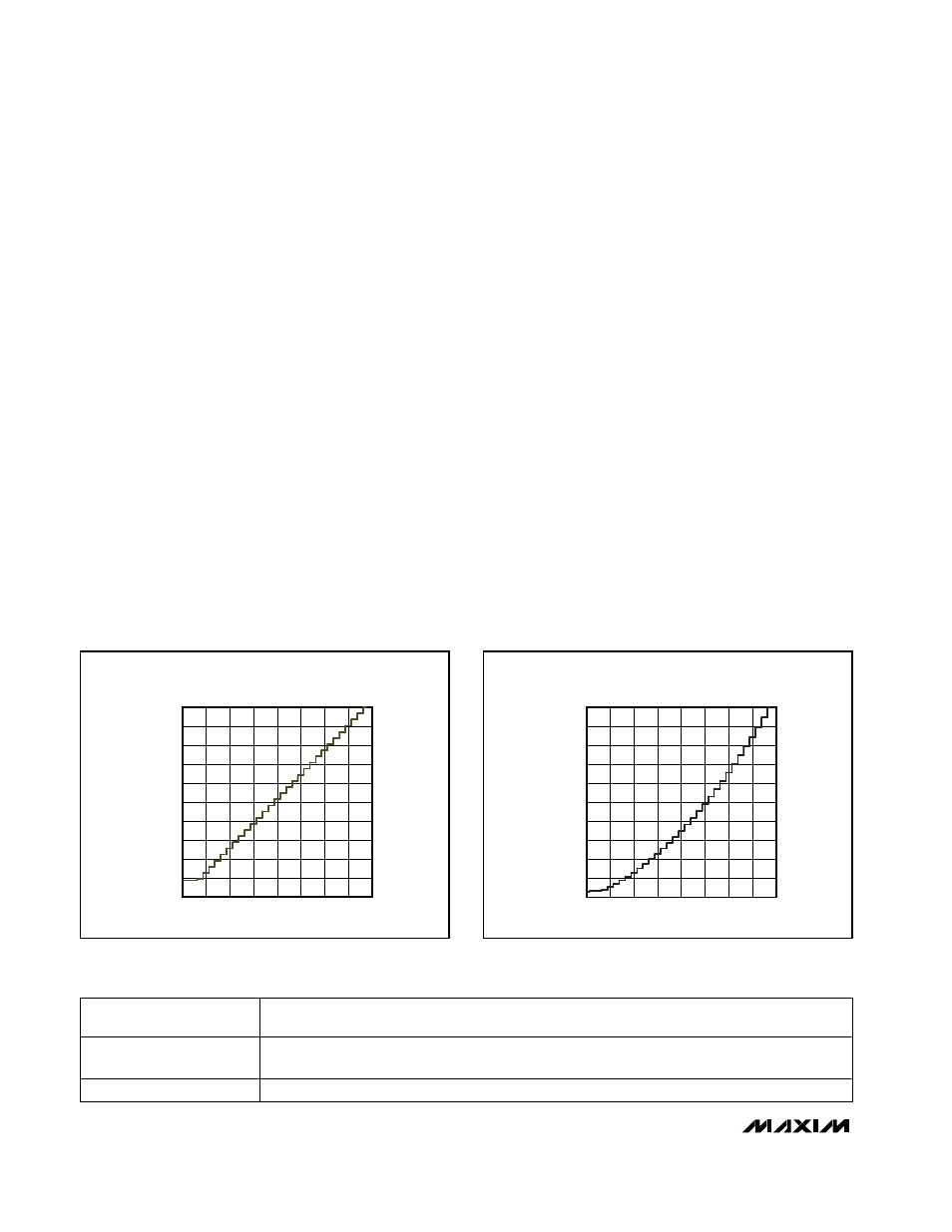
brightness code of ob00000 corresponds to a 9.375%
DPWM duty cycle, and a brightness code of ob11111
corresponds to a 100% DPWM duty cycle. The duty
cycle changes by 3.125% per step, except codes
ob00000 to ob00011 all produce 9.375% (Figure 3).
To disable DPWM and always use 100% duty cycle, set
V
MINDAC
to VL. Note that with DPWM disabled, the
equations above should assume V
MINDAC
= 0 instead
of V
MINDAC
= VL. Table 2 lists MINDAC’s functionality,
and Table 3 shows some typical settings for the bright-
ness adjustment.
In normal operation, V
MINDAC
is set between 0 and
V
REF
, and the MAX1739/MAX1839 use both lamp cur-
rent control and DPWM control to vary the lamp bright-
ness (Figure 4). In this mode, lamp current control
regulates the average lamp current during a DPWM on-
cycle and not the overall average lamp current.
Analog Interface and Brightness Code
The MAX1739/MAX1839 analog interface uses an inter-
nal ADC with 1-bit hysteresis to generate the brightness
code used to dim the lamp (see Dimming Range).
CTL/SDA is the ADC’s input, and CRF/SCL is its refer-
ence voltage. The ADC can operate in either positive-
scale ADC mode or negative-scale ADC mode. In
positive-scale ADC mode, the brightness code increas-
es from 0 to 31 as V
CTL
increases from 0 to V
CRF
. In
negative-scale mode, the brightness scale decreases
from 31 to 0 as V
CTL
increases from 0 to V
CRF
(Figure 5).
The analog interface’s internal ADC uses 1-bit hystere-
sis to keep the lamp from flickering between two codes.
V
CTL
’s positive threshold (V
CTL(TH)
) is the voltage
required to transition the brightness code as V
CTL
increases and can be calculated as follows:
V
CTL(TH)
= (n + 2) / 33 V
CRF
(positive-scale ADC mode, MODE = GND)
V
CTL(TH)
= (33 - n) / 33 V
CRF
(negative-scale ADC mode, MODE = REF)
where n is the current selected brightness code. V
CTL
’s
negative threshold is the voltage required to transition
the brightness code as V
CTL
decreases and can be
calculated as follows:
V
CTL(TH)
= n / 33 V
CRF
(positive-scale ADC mode, MODE = GND)
V
CTL(TH)
= (31 - n) / 33 V
CRF
(negative-scale ADC mode, MODE = REF)
Figure 5 shows a graphic representation of the thresh-
olds. CRF/SDA’s and CTL/SCL’s input voltage range is
2.7V to 5.5V.
MINDAC = VL
DPWM disabled (always on 100% duty cycle). Operates in lamp current control only.
(Use V
MINDAC
= 0 in the equations.)
MINDAC = REF
DPWM control enabled, duty cycle ranges from 9% to 100%. Lamp current control is disabled
(always maximum current).
0
≤ V
MINDAC
< VREF
The device uses both lamp current control and DPWM.
Table 2. MINDAC Functionality
0
10
20
30
60
70
40
50
80
90
100
0
12
4
8
20
16
24
28
32
BRIGHTNESS CODE
DPWM DUTY CYCLE (%)
DPWM SETTINGS
Figure 3. DPWM Settings
0
10
20
30
60
70
40
50
80
90
100
0
12
4
8
20
16
24
28
32
BRIGHTNESS CODE
COMBINED POWER LEVEL (%)
COMBINED POWER LEVEL
(BOTH DPWM AND
LAMP CONTROL CURRENT)
Figure 4. Combined Power Level