Wide brightness range ccfl backlight controllers – Rainbow Electronics MAX1839 User Manual
Page 15
MAX1739/MAX1839
†
Wide Brightness Range
CCFL Backlight Controllers
______________________________________________________________________________________
15
See Digital Interface for instructions on using the
SMBus interface.
Synchronizing the DPWM Frequency
MODE has two functions: one is to select the interface
mode as described in Interface Selection, and the other
is to synchronize the DPWM “chopping” frequency to
an external signal to prevent unwanted effects in the
display screen.
To synchronize the DPWM frequency, connect MODE
to VL, REF, or GND through a 10k
Ω resistor. Then con-
nect a 500pF capacitor from an AC signal source to
MODE as shown in Figure 6. The synchronization range
is from 32kHz to 100kHz, which corresponds to a
DPWM frequency range of 250Hz to 781Hz (128 MODE
pulses per DPWM cycle). High DPWM frequencies limit
the dimming range. See Loop Compensation for more
information concerning high DPWM frequencies.
Royer Oscillator MOSFET Drivers
The MAX1739/MAX1839 directly drive the two external
MOSFETs used in the Royer oscillator. This has many
advantages over the traditional method that uses bipo-
lar switching and an extra winding on the transformer.
Directly driving the MOSFET eliminates the need for an
extra winding on the transformer, which reduces cost
and minimizes the size of the transformer. Also, driving
the switches directly improves commutation efficiency
and commutation timing. Using MOSFETs for the
switches typically improves overall inverter efficiency
due to lower switch drops.
The Royer topology works as a zero voltage crossing
(ZVC) detector and switches currents between the two
sections of the transformer primary windings. The two
windings work alternately, each generating a half wave
that is transferred to the secondary to produce the full-
wave sinusoidal lamp voltage and current. The
MAX1739/MAX1839 detect the zero crossing through
the SYNC pin; the threshold is set at 500mV referred to
CS and has a typical delay of 50ns. The active switch-
ing forces commutation very close to the ZVC point and
has better performance than the traditional winding-
based ZVC switchover. Commutation can be further
BRIGHTNESS
POSITIVE-
SCALE ADC
NEGATIVE-
SCALE ADC
SMBus
DAC
OUTPUT
DPWM DUTY
CYCLE
(%)
COMBINED
POWER
LEVEL (%)
Maximum
Brightness
MODE = GND,
V
CTL/SCL
=
V
CRF/SDA
MODE = REF,
V
CTL/SCL
= 0
Bright [4:0] =
ob11111
Full-scale
DAC OUTPUT =
195.83mV
100
100
Minimum
Brightness
MODE = GND,
V
CTL/SCL
= 0,
V
MINDAC
=
VREF / 3
MODE = REF,
V
CTL/SCL
= V
CRF/SDA
,
V
MINDAC
= VREF / 3
Bright [4:0] =
ob00000,
V
MINDAC
=
VREF / 3
Zero-scale
DAC OUTPUT =
V
MINDAC
/ 10
9
3
Table 3. Brightness Adjustment Ranges (for 33:1 Dimming)
Note: The current-level range is solely determined by the MINDAC-to-REF ratio and is externally set.
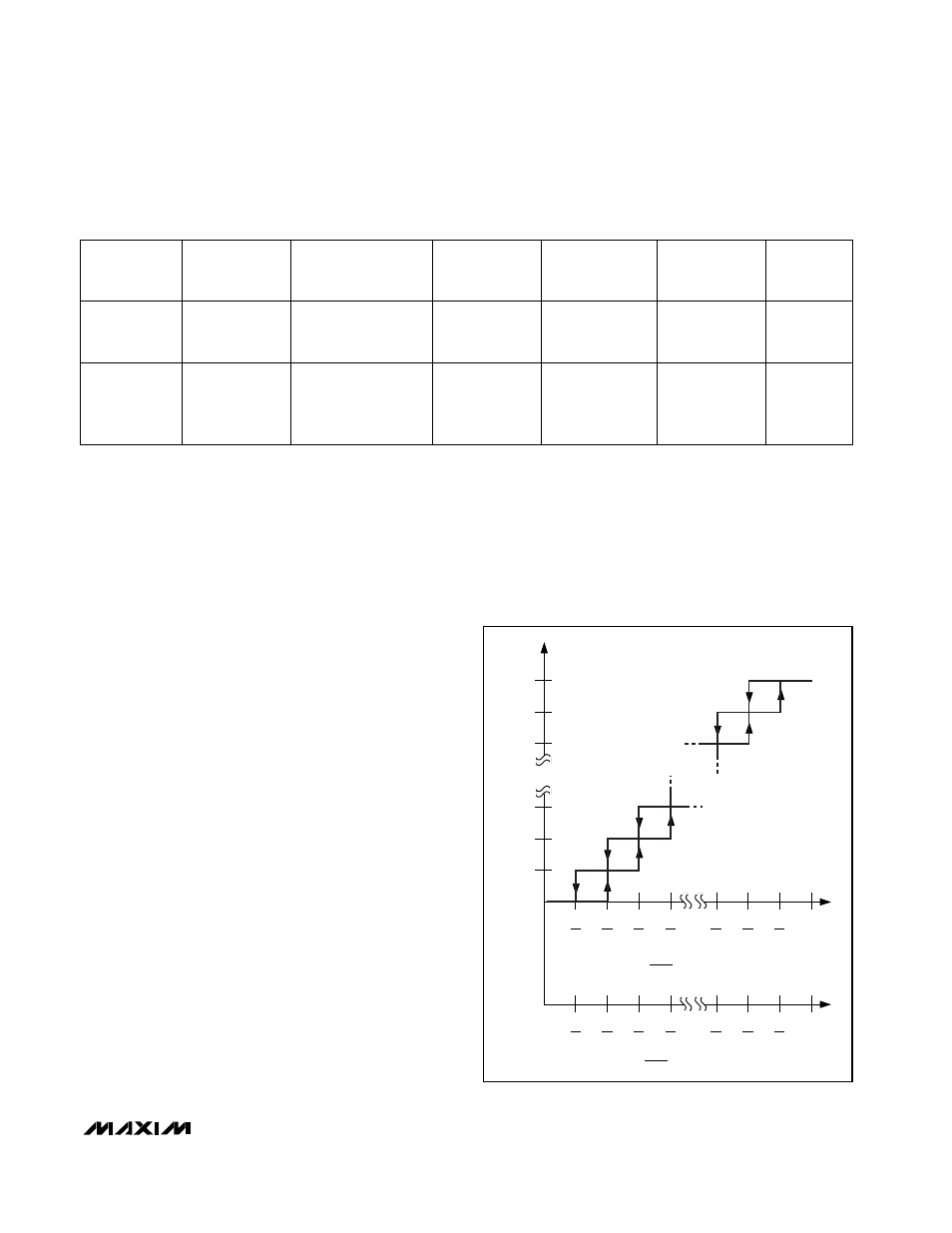
BRIGHTNESS CODE
31
30
29
3
2
1
0
1
33
2
33
3
33
4
33
V
CTL
V
CRF
(MODE = GND)
V
CTL
V
CRF
(MODE = REF)
30
33
31
33
32
33
1
32
33
31
33
30
33
29
33
3
33
2
33
1
33
0
1
Figure 5. Brightness Code