Rainbow Electronics MAX1362 User Manual
Page 22
MAX1361/MAX1362
MAX1361/MAX1362’s INL is measured using the end-
point method.
Differential Nonlinearity
Differential nonlinearity (DNL) is the difference between
an actual step width and the ideal value of 1 LSB. A
DNL error specification of less than 1 LSB guarantees
no missing codes and a monotonic transfer function.
Aperture Jitter
Aperture jitter (t
AJ
) is the sample-to-sample variation in
the time between the samples.
Aperture Delay
Aperture delay (t
AD
) is the time between the falling
edge of the sampling clock and the instant when an
actual sample is taken.
Signal-to-Noise Ratio
For a waveform perfectly reconstructed from digital
samples, the theoretical maximum SNR is the ratio of
the full-scale analog input (RMS value) to the RMS
quantization error (residual error). The ideal, theoretical
minimum analog-to-digital noise is caused by quantiza-
tion error only and results directly from the ADC’s reso-
lution (N bits):
SNR (MAX)[dB] = 6.02dB x N + 1.76dB
In reality, there are other noise sources besides quanti-
zation noise: thermal noise, reference noise, clock jitter,
etc. SNR is computed by taking the ratio of the RMS
signal to the RMS noise, which includes all spectral
components minus the fundamental, the first five har-
monics, and the DC offset.
Signal-to-Noise Plus Distortion
Signal-to-noise plus distortion (SINAD) is the ratio of the
fundamental input frequency’s RMS amplitude to RMS
equivalent of all other ADC output signals.
SINAD(dB) = 20 x log (SignalRMS / NoiseRMS)
Effective Number of Bits
Effective number of bits (ENOB) indicates the global
accuracy of an ADC at a specific input frequency and
sampling rate. An ideal ADC’s error consists of quanti-
zation noise only. With an input range equal to the
ADC’s full-scale range, calculate the ENOB as follows:
ENOB = (SINAD - 1.76) / 6.02
Total Harmonic Distortion
Total harmonic distortion (THD) is the ratio of the RMS
sum of the input signal’s first five harmonics to the fun-
damental itself. This is expressed as:
where V
1
is the fundamental amplitude, and V
2
through
V
5
are the amplitudes of the 2nd- through 5th-order
harmonics.
THD
V
V
V
V
V
=
×
+
+
+
⎛
⎝
⎜
⎜
⎜
⎞
⎠
⎟
⎟
⎟
20
2
2
3
2
4
2
5
2
1
log
SINAD dB
Signal
Noise
THD
RMS
RMS
RMS
(
)
log
=
×
+
⎡
⎣
⎢
⎢
⎤
⎦
⎥
⎥
20
4-Channel, 10-Bit, System Monitor with Programmable
Trip Window and SMBus Alert Response
22
______________________________________________________________________________________
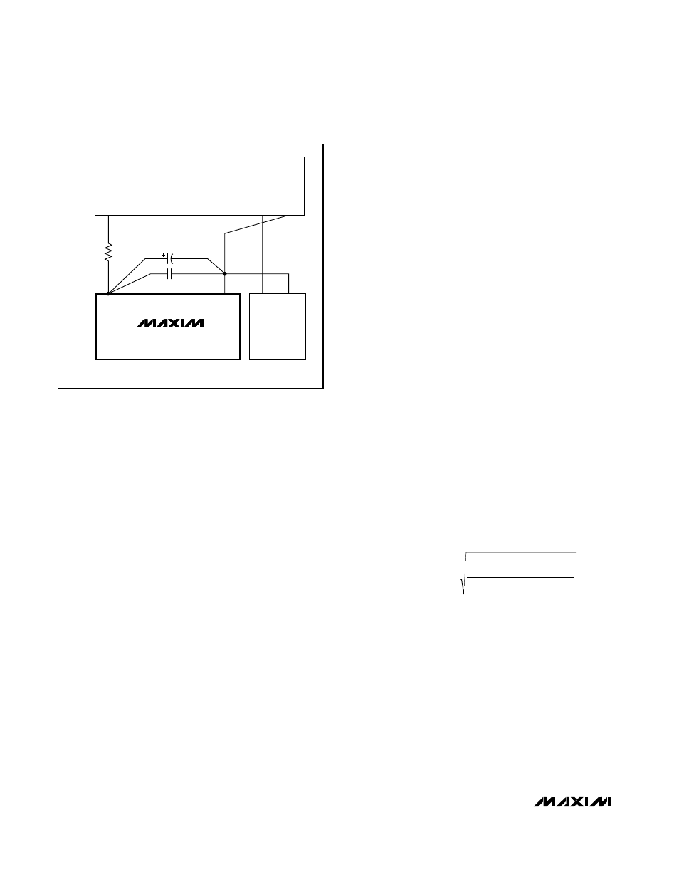
GND
V
LOGIC
= 3V / 5V
3V OR 5V
SUPPLIES
DGND
3V/5V
GND
*OPTIONAL
4.7
µF
R* = 5
Ω
0.1
µF
V
DD
DIGITAL
CIRCUITRY
MAX1361
MAX1362
Figure 16. Power-Supply Grounding Connection