Table 13. readback-mode format, Table 14. reading in monitor-mode data format, Table 15. alarm-status register – Rainbow Electronics MAX1362 User Manual
Page 20
MAX1361/MAX1362
To disable alarming on a specific channel, set the lower
threshold to 0x800 and the upper threshold to 0x7FF for
bipolar mode, or set the lower threshold to 0x000 and
the upper threshold to 0xFFF for unipolar mode.
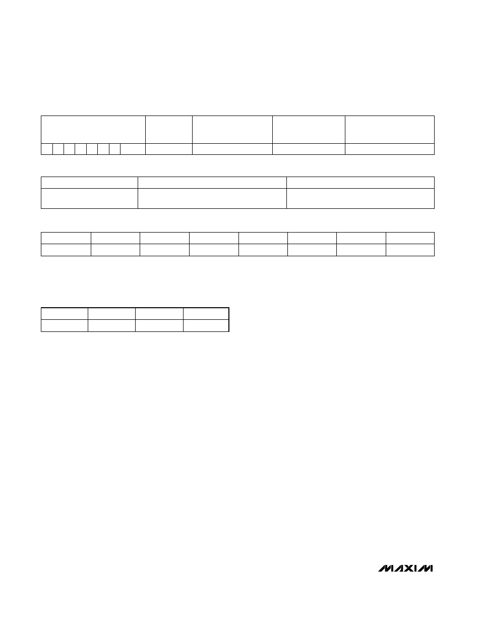
Readback Mode
Select readback mode by setting CS3, CS2 to [1,1] in
the configuration byte. Begin a read operation to start
reading back monitor-setup data. Clock out delay bit
settings, INT_EN bit, and the lower and upper thresh-
olds programmed for each channel. Readback mode
follows exactly the same format as writing to the moni-
tor-setup data, with the exception of the first 4 alarm-
reset bits, which are always 1 (Table 13).
Reading in Monitor Mode
Reading in monitor mode reads back the alarm-status
register, latched-fault register, and current-conversion
results as shown in Table 14.
The MAX1361/MAX1362 register pointer loops back to
the beginning of the current-conversion result after
reading the last conversion result. Stop reading at any
time by asserting a STOP condition or NACK.
Note:
The MAX1361/MAX1362 do not update the cur-
rent-conversion results register while reading in monitor
mode. Monitor mode resumes after a STOP condition or
NACK.
Alarm-Status Register
The latched-fault register records a snapshot of the
alarming channel at the instance that a fault condition is
asserted. An alarm-status bit of 1 (Table 15) indicates a
fault, and the data in the latched-fault register of the
corresponding channel contains the conversion result
that caused the alarm to trip. Resetting alarms does not
clear the latched-fault register, thus the latched-fault
register contains valid data only if an alarm status bit is
high for the given channel.
The current-conversion register contains the most
recent conversion results. If the user attempts to read
past the last result of the current-conversion register,
the MAX1361/MAX1362 wraps back to the beginning of
the current-conversion result.
The latched-fault register and current-conversion regis-
ter follow the data format detailed in Tables 8 and 16.
Register length depends on the number of conversions
in one monitoring sequence. For example, when chan-
nel pairs 0/1 and channels 2/3 are monitored differen-
tially, there are only two conversion results to report. The
latched-fault register is 2 x 16 bits long, after which two
current-conversion results follow. Likewise, if CS0 and
CS1 limit the upper bound of the channel scan range
from CH0 to CH2 in single-ended mode, the latched-
fault register clocks out 3 x 16 bits of data followed by
the current-conversion results, also 3 x 16 bits.
4-Channel, 10-Bit, System Monitor with Programmable
Trip Window and SMBus Alert Response
20
______________________________________________________________________________________
SCAN SPEED AND INT_EN
AIN0
THRESHOLDS
AIN1 THRESHOLDS
(SKIP IF DIFFERENTIAL
MODE OR CS1, CS0 < 1)
AIN2 THRESHOLDS
(SKIP IF CS1, CS0 < 2)
AIN3 THRESHOLDS
(SKIP IF DIFFERENTIAL
MODE OR CS1, CS0 < 3)
1
1
1
1 D2 D1 D0 INT_EN
24 bits
24 bits
24 bits
24 bits
Table 13. Readback-Mode Format
ALARM-STATUS REGISTER
LATCHED-FAULT REGISTER
CURRENT-CONVERSION RESULTS
8 bits
16, 32, 48, or 64 bits (depends on CSO, CS1,
and SE/DIF
)
16, 32, 48, or 64 bits (depends on CSO, CS1,
and SE/DIF
)
Table 14. Reading in Monitor-Mode Data Format
CH0 UP
CH0 LOW
CH1 UP
CH1 LOW
CH2 UP
CH2 LOW
CH3 UP
CH3 LOW
0/1
0/1
0/1
0/1
0/1
0/1
0/1
0/1
Table 15. Alarm-Status Register
0 = Not-alarm condition.
1 = Alarm condition.
AIN0
AIN1
AIN2
AIN3
16-bit read
16-bit read
16-bit read
16-bit read
Table 16. Latched-Fault and Current-
Conversion Register