Table 1. i, C slave selection table – Rainbow Electronics MAX1362 User Manual
Page 13
To generate a not-acknowledge condition, the receiver
allows SDA to be pulled high before the rising edge of
the acknowledge-related clock pulse, and leaves SDA
high during the high period of the clock pulse.
Monitoring the acknowledge bits allows for detection of
unsuccessful data transfers. An unsuccessful data
transfer happens if a receiving device is busy or if a
system fault has occurred. In the event of an unsuc-
cessful data transfer, the bus master reattempts com-
munication at a later time.
Slave Address
The MAX1361/MAX1362 have a 7-bit I
2
C slave
address. The slave address is selected using A0. The
MAX1361/MAX1362 (EUB, MEUB, and LEUB) have 3
base address options, allowing up to 6 devices concur-
rently per I
2
C bus (see Table 1).
The MAX1361/MAX1362 continuously wait for a START
condition followed by its slave address. When the device
recognizes its slave address, it is ready to accept or
send data depending on the R/W bit (Figure 6).
HS I
2
C Mode
At power-up, the MAX1361/MAX1362 bus timing is set
for fast mode (F/S mode, up to 400kHz I
2
C clock), which
limits the conversion rate to approximately 22ksps.
Switch to high-speed mode (HS mode, up to 1.7MHz
I
2
C clock) to achieve conversion rates up to 94.4ksps.
The MAX1361/MAX1362 convert up to 150ksps in moni-
tor mode, regardless of I
2
C mode. If conversion results
are unread, I
2
C bandwidth limitations do not apply in
monitor mode.
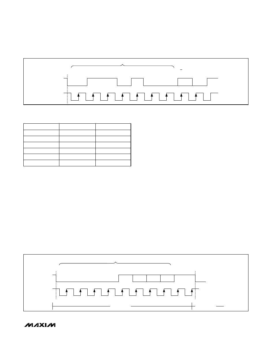
Select HS mode by addressing all devices on the bus
with the HS-mode master code 0000 1XXX (X = don’t
care). After successfully receiving the HS-mode master
code, the MAX1361/MAX1362 issue a NACK, allowing
SDA to be pulled high for one clock cycle (Figure 7).
After the NACK, the MAX1361/MAX1362 operate in HS
mode. Send a repeated START (Sr) followed by a slave
address to initiate HS-mode communication. If the mas-
ter generates a STOP condition the MAX1361/MAX1362
MAX1361/MAX1362
4-Channel, 10-Bit, System Monitor with Programmable
Trip Window and SMBus Alert Response
______________________________________________________________________________________
13
0
1
1
1
0
0
0
R/W
ACK
SLAVE ADDRESS
S
SCL
SDA
1
2
3
4
5
6
7
8
9
Figure 6. MAX1361/MAX1362 Slave Address Byte
A0 STATE
SUFFIX
ADDRESS
Low
EUB
0110100
High
EUB
0110101
Low
MEUB
0110110
High
MEUB
0110111
Low
LEUB
0110010
High
LEUB
0110011
Table 1. I
2
C Slave Selection Table
0
0
0
1
0
X
X
X
NACK
HS-MODE MASTER CODE
SCL
SDA
S
Sr
F/S MODE
HS MODE
Figure 7. F/S-Mode to HS-Mode Transfer