Table 9. monitor-mode setup data format, Table 11. delay settings, Table 12. lower and upper threshold data format – Rainbow Electronics MAX1362 User Manual
Page 19
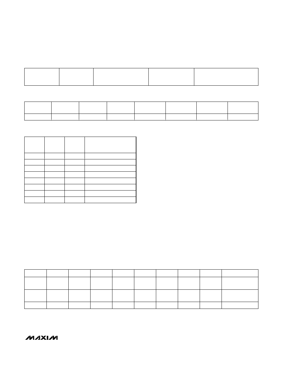
A 1 written to the reset alarm CH_ clears the alarm, oth-
erwise no action occurs (Table 10). Deassert INT by
clearing all alarms or by initiating an SMBus alert dur-
ing an alarm condition (see the SMBus Alert section)
The Delay 2, Delay 1, Delay 0 bits set the speed of
monitoring by changing the delay between conver-
sions. Delay 2, 1, 0 = 000 sets the maximum possible
speed; 001 divides the maximum speed by ~2.
Increasing delay values further divides the previous
speed by two (Table 11).
INT_EN controls the open-drain INT output. Set INT_EN
to 1 to enable the hardware interrupt. Set INT_EN to 0
to disable the hardware interrupt output. The INT output
is high impedance when disabled or when there are no
alarms. The master can also poll the alarm status regis-
ter at any time to check the alarm status.
Repeat clocking channel threshold data up to the chan-
nel programmed by CS1 and CS0 (Table 12). For differ-
ential input mode, omit odd channels; the lower and
upper threshold data applies to channel pairs. There is
no need to clock in dummy data for odd (or even)
channels (Table 6).
MAX1361/MAX1362
4-Channel, 10-Bit, System Monitor with Programmable
Trip Window and SMBus Alert Response
______________________________________________________________________________________
19
Alarm reset, scan
speed, INT_EN ,
(8 bits)
AIN0 thresholds
(24 bits)
AIN1 thresholds
(skip if differential mode, or
CS1, CS0 < 1) (24 bits)
AIN2 thresholds (skip if
CS1, CS0 < 2)
(24 bits)
AIN3 thresholds (skip if differential
mode, or CS1, CS0 < 3)
(24 bits)
Table 9. Monitor-Mode Setup Data Format
RESET
ALARM CH 0
RESET
ALARM CH 1
RESET
ALARM CH 2
RESET
ALARM CH 3
DELAY 2
DELAY 1
DELAY 0
INT_EN
0/1
0/1
0/1
0/1
0/1
0/1
0/1
0/1
Table 10. Alarm Reset, Scan Speed Register, and INT_EN Data Format
DELAY 2 DELAY 1
DELAY 0
MONITOR-MODE
CONVERSION RATE
(ksps)
0
0
0
150.0*
0
0
1
75.0
0
1
0
37.5
0
1
1
18.8
1
0
0
9.4
1
0
1
4.7
1
1
0
2.3
1
1
1
1.2
Table 11. Delay Settings
*When using delay = [0,0,0] in internal reference mode and
AIN3/REF configured as a REF output, the MAX1361/MAX1362
may exhibit a code-dependant gain error due to insufficient
internal reference drive. Gain error caused by this phenomenon
is typically less than 1%FSR (0.1µF C
REF
in series with a 2k
Ω
resistor) and increases with a larger C
REF
. Avoid this gain error
by using an external reference, V
DD
, as a reference or use an
internal reference with AIN3/REF as an analog input (see Table
4). Alternatively, choose delay bits other than [0,0,0] to lower the
conversion rate.
BYTE
B7
B6
B5
B4
B3
B2
B1
B0
ACKNOWLEDGE
1
X
X
LT9
(MSB)
LT8
LT7
LT6
LT5
LT4
ACK
2
LT3
LT2
LT1
LT0 (LSB)
X
X
UT9
(MSB)
UT8
ACK
3
UT7
UT6
UT5
UT4
UT3
UT2
UT1
UT0 (LSB)
ACK
Table 12. Lower and Upper Threshold Data Format
X = Don’t care.
ACK = Acknowledge.