Table 2. configuration byte format – Rainbow Electronics MAX1362 User Manual
Page 14
MAX1361/MAX1362
4-Channel, 10-Bit, System Monitor with Programmable
Trip Window and SMBus Alert Response
14
______________________________________________________________________________________
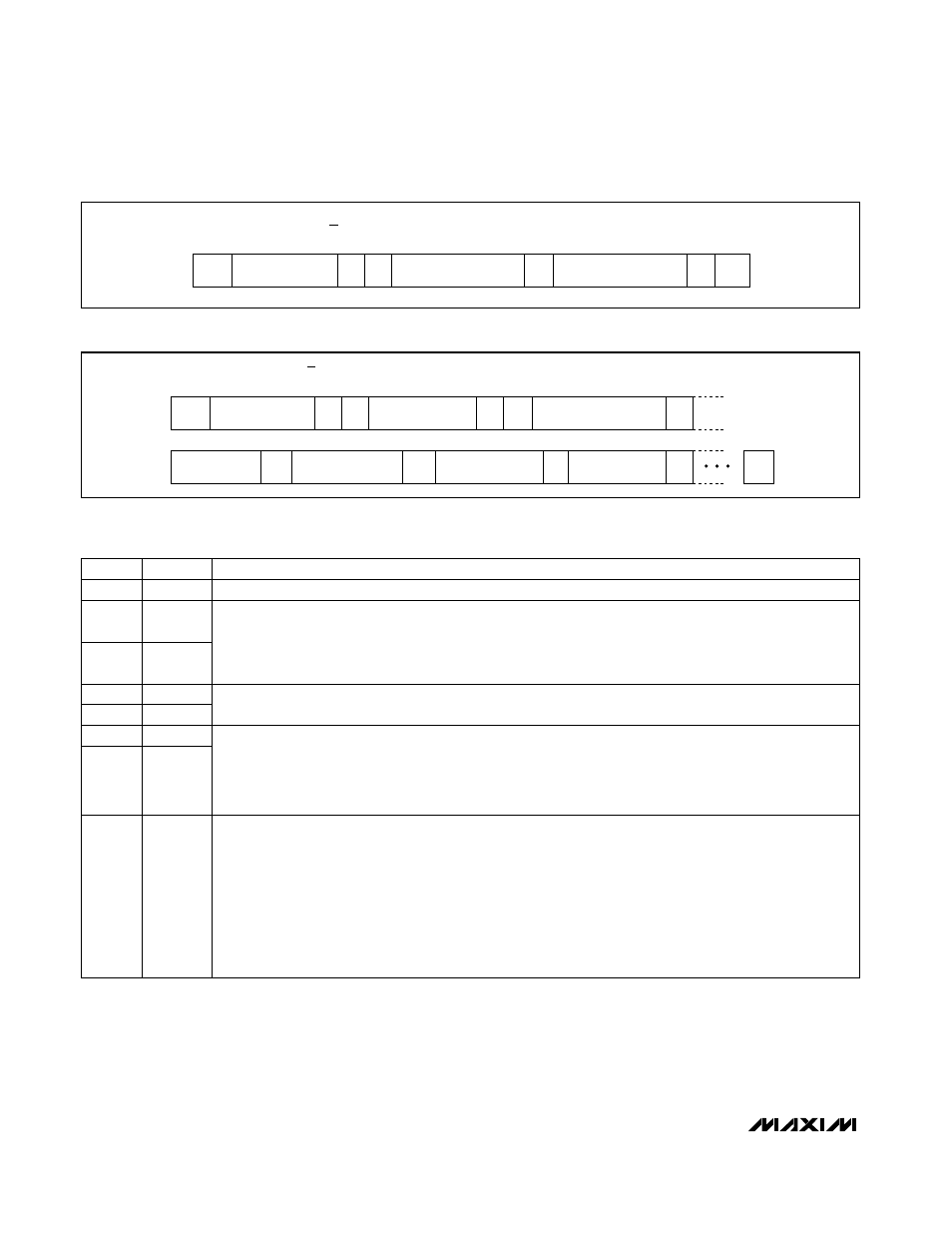
START
CONDITION
START
ADDRESS
FROM THE MASTER
CONFIGURATION
BYTE FROM THE MASTER
SETUP
BYTE FROM THE MASTER
0
A
A
A
STOP
R/W BIT FROM
THE MASTER
Figure 8. Example of Writing Setup and Control Bytes
START
CONDITION
START
ADDRESS
FROM THE MASTER
SETUP BYTE
FROM THE MASTER
MONITOR
SETUP BIT
ALARM RESET, SCAN
SPEED, INT_EN
0
A
1
A
A
CH 0 LT [11:4]
CH 0 LT [3:0]; UT [11:8]
CH 1 LT [11:4]
CH 0 UT [7:0]
A
A
A
A
STOP
R/W BIT FROM
THE MASTER
Figure 9. Example of Extended Setup-Byte Writing
BIT
NAME
DESCRIPTION
7(MSB)
CONFIG
The configuration byte always starts with 0.
6
SCAN1
5
SCAN0
SCAN1, SCAN0 = [0,0], scans from channel 0 to the upper channel chosen by CS1, CS0.
SCAN1, SCAN0 = [0,1], converts a single channel chosen by CS1, CS0 eight times.
SCAN1, SCAN0 = [1,0] monitor mode monitors from channel 0 to the upper channel chosen by CS1, CS0.
SCAN1, SCAN0 = [1,1], single channel conversion for the channel is chosen by CS0, CS1.
4
CS3
3
CS2
CS3, CS2 = [1,1] enables readback of monitor-mode setup data.
2
CS1
1
CS0
Selects the upper limit of the channel range used for the conversion sequence in scan modes SCAN = [0,0]
and monitor modes SCAN = [1,0].
Selects the conversion channel when SCAN = [0,1] or when SCAN = [1,1].
(Tables 5 and 6)
0
SE/DIF
1 = single-ended inputs.
0 = differential inputs.
AIN0 and AIN1 form the first differential pair and AIN2 and AIN3 form the second differential pair. (See Tables
4 and 5.)
Selects single-ended or differential conversions. In single-ended mode, input signal voltages are referenced
to GND. In differential mode, the voltage difference between two channels is measured.
When single-ended mode is used, the MAX1361/MAX1362 perform unipolar conversions regardless of the
UNI/BIP bit in the setup byte.
(Table 7)
Table 2. Configuration Byte Format*
*Power-on defaults: 0x01