Pin description – Rainbow Electronics MAX2325 User Manual
Page 5
MAX2323/MAX2325
Triple/Dual-Mode
CDMA LNA/Mixers
_______________________________________________________________________________________
5
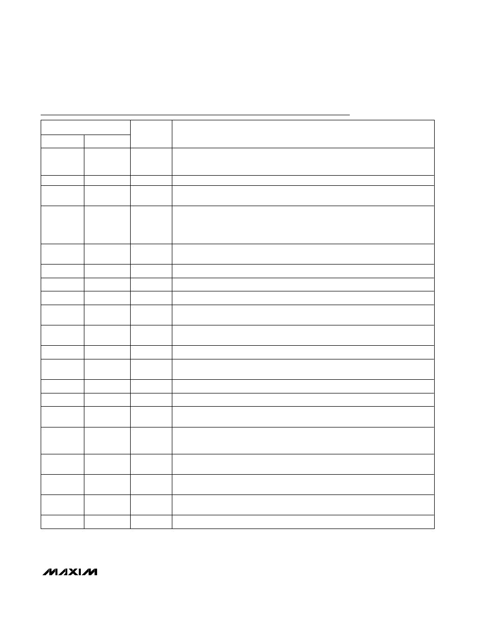
Pin Description
PIN
MAX2323
MAX2325
NAME
FUNCTION
1
1
RLNA
L N A B i a s - S e t t i ng P i n . F o r no m i n a l b i a s , c o n n ec t a 24 k
Ω r es i s t o r t o g r o u n d . T h i s
r e si s t o r v a l u e c a n b e a d j u st e d t o a l t e r t h e l i n e a r i t y o f t h e i np u t L N A i n hi g h - g ai n ,
h i g h - l i n ea r i t y C D M A m o d e s .
—
2, 10, 23
N.C.
No Connection. Leave this pin floating.
2
—
PLNAIN
High-Band RF Input Port. Blocking capacitor is required, which may be used as part of
the matching network.
3, 8, 11,
12, 13, 18,
24, 25, 27
3, 8, 11, 12,
13, 17, 18,
24, 25, 27
GND
Ground
4
4
CLNAIN
Low-Band RF Input Port. Blocking capacitor is required, which may be used as part of
the matching network.
5
5
SLEEP
Logic Input. High shuts off entire device.
6
6
G2
Logic Input. See Tables 1 and 2 for details.
7
7
G1
Logic Input. See Tables 1 and 2 for details.
9
9
LOLIN
Low-Frequency LO Input Port. Requires blocking capacitor, which may be used as
part of an optional matching network.
10
—
LOHIN
High-Frequency LO Input Port. Requires blocking capacitor, which may be used as
part of an optional matching network.
14
14
MODE
Logic Input. See Tables 1 and 2 for details.
15
15
FMOUT
FM IF Output Port. Requires a pull-up inductor and a DC blocking capacitor, which
may be used as part of the matching network.
16
16
V
CC
2.7V to 3.6V Supply Pin. Must be capacitively bypassed near the pin.
17
—
BAND
Logic Input. High selects high band (PCS). Low selects low band (cellular).
19, 20
19, 20
CDMA-,
CDMA+
Differential Output Port for CDMA Mode. Requires pull-up inductors and blocking
capacitors, which may be used as part of the matching network.
21
21
RBIAS
Bias Setting Pin. For nominal bias, connect a 20k
Ω resistor to ground. This resistor
value can be adjusted to alter the linearity of the mixers in all modes and the LNA in all
modes except high gain and high linearity.
22
22
CMIXIN
Low-Band Mixer Input Port. Requires blocking capacitor, which may be used as part of
the matching network.
23
—
PMIXIN
High-Band Mixer Input Port. Requires blocking capacitor, which may be used as part
of the matching network.
26
—
PLNAOUT
High-Band LNA Output Port. This port requires an external pull-up inductor and series
capacitor as part of the matching network.
—
26
V
CC
2.7 to 3.6V Supply Pin. Bypassing is not necessary at this pin.