Max1422, Functional diagram – Rainbow Electronics MAX1422 User Manual
Page 14
MAX1422
Total Harmonic Distortion (THD)
THD is typically the ratio of the RMS sum of the first four
harmonics of the input signal to the fundamental itself.
This is expressed as:
where V
1
is the fundamental amplitude, and V
2
through
V
5
are the amplitudes of the 2nd- through 5th-order
harmonics.
Spurious-Free Dynamic Range (SFDR)
SFDR is the ratio expressed in decibels of the RMS
amplitude of the fundamental (maximum signal compo-
nent) to the RMS value of the next largest spurious
component, excluding DC offset.
Intermodulation Distortion (IMD)
The two-tone IMD is the ratio expressed in decibels of
either input tone to the worst 3rd-order (or higher) inter-
modulation products. The individual input tone levels
are at -6.5dB full scale and their envelope is at -0.5dB
full scale.
THD
V
V
V
V
V
=
×
+
+
+
20
10
2
2
3
2
4
2
5
2
1
log
12-Bit, 20Msps, +3.3V, Low-Power ADC with
Internal Reference
14
______________________________________________________________________________________
MAX1422
1nF
1k
Ω
100
Ω
100
Ω
C
IN
22pF
CML
C
IN
22pF
INP
INN
0.1
µF
R
ISO
50
Ω
R
ISO
50
Ω
0.22
µF
V
IN
MAX4108
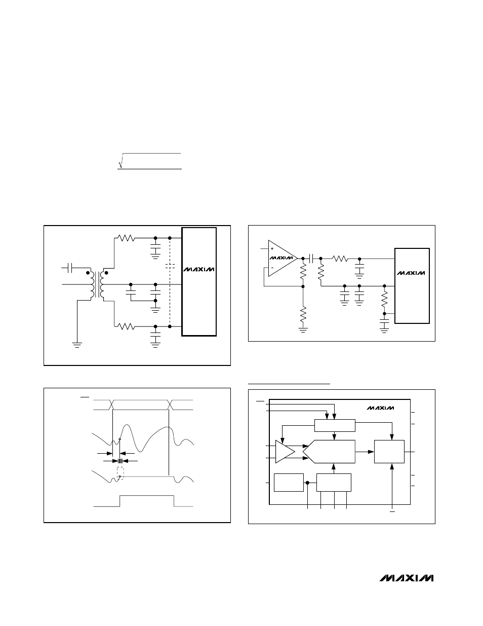
Figure 9. Single-Ended AC-Coupled Input
MAX1422
T1
N.C.
V
IN
6
1
5
2
4
3
22pF
22pF
1nF
0.1
µF
0.22
µF
25
Ω
25
Ω
MINICIRCUITS
T1–1T–KK81
INN
INP
CML
44pF
*
*
*
*REPLACE BOTH 22pF CAPS WITH 44pF BETWEEN
INP AND INN TO IMPROVE DYNAMIC PERFORMANCE.
Figure 8. Using a Transformer for AC-Coupling
HOLD
ANALOG
INPUT
SAMPLED
DATA (T/H)
T/H
t
AD
t
AJ
TRACK
TRACK
CLK
CLK
Figure 10. T/H Aperature Timing
CLK
INP
INTERFACE
PIPELINE ADC
OUTPUT
DRIVERS
REFIN REFP CML REFN
OE
AV
DD
AGND
DV
DD
DGND
D11–D0
INN
PD
T/H
MAX1422
BANDGAP
REFERENCE
CLK
REF SYSTEM +
BIAS
Functional Diagram