Rainbow Electronics MAX1422 User Manual
Page 13
Aperture Delay
Aperture delay (t
AD
) is the time defined between the
falling edge of the sampling clock and the instant when
an actual sample is taken (Figure 10).
Signal-to-Noise Ratio (SNR)
For a waveform perfectly reconstructed from digital
samples, the theoretical maximum SNR is the ratio of
the full-scale analog input (RMS value) to the RMS
quantization error (residual error). The ideal, theoretical,
minimum analog-to-digital noise is caused by quantiza-
tion error only and results directly from the ADCs reso-
lution (N-Bits):
SNR
(MAX)
= (6.02
✕
N + 1.76)dB
In reality, there are other noise sources besides quanti-
zation noise e.g., thermal noise, reference noise, clock
jitter, etc. SNR is computed by taking the ratio of the
RMS signal to the RMS noise, which includes all spec-
tral components minus the fundamental, the first four
harmonics, and the DC offset.
Signal-to-Noise Plus Distortion (SINAD)
SINAD is computed by taking the ratio of the RMS sig-
nal to all spectral components minus the fundamental
and the DC offset.
Effective Number of Bits (ENOB)
ENOB specifies the dynamic performance of an ADC at
a specific input frequency and sampling rate. An ideal
ADCs error consists of quantization noise only. ENOB is
computed from:
ENOB
SINADdB
dB
DdB
=
-
1 76
6 02
.
.
MAX1422
12-Bit, 20Msps, +3.3V, Low-Power ADC with
Internal Reference
______________________________________________________________________________________
13
INPUT
300
Ω
-5V
+5V
0.1
µF
0.1
µF
0.1
µF
C
IN
*
22pF
C
IN
*
22pF
1nF
0.22
µF
44pF*
R
ISO
50
Ω
R
ISO
50
Ω
-5V
600
Ω
300
Ω
300
Ω
INP
INN
LOWPASS FILTER
CML
600
Ω
+5V
-5V
0.1
µF
300
Ω
300
Ω
600
Ω
300
Ω
0.1
µF
0.1
µF
0.1
µF
+5V
0.1
µF
300
Ω
MAX4108
MAX1422
MAX4108
MAX4108
LOWPASS FILTER
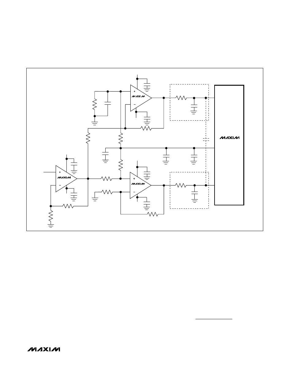
*TWO C
IN
(22pF) CAPS MAY BE REPLACED BY
ONE 44pF CAP, TO IMPROVE PERFORMANCE.
Figure 7. Typical Application Circuit for Single-Ended to Differential Conversion