Dc electrical characteristics (continued) – Rainbow Electronics MAX3079E User Manual
Page 3
MAX3070E–MAX3079E
+3.3V, ±15kV ESD-Protected, Fail-Safe,
Hot-Swap, RS-485/RS-422 Transceivers
_______________________________________________________________________________________
3
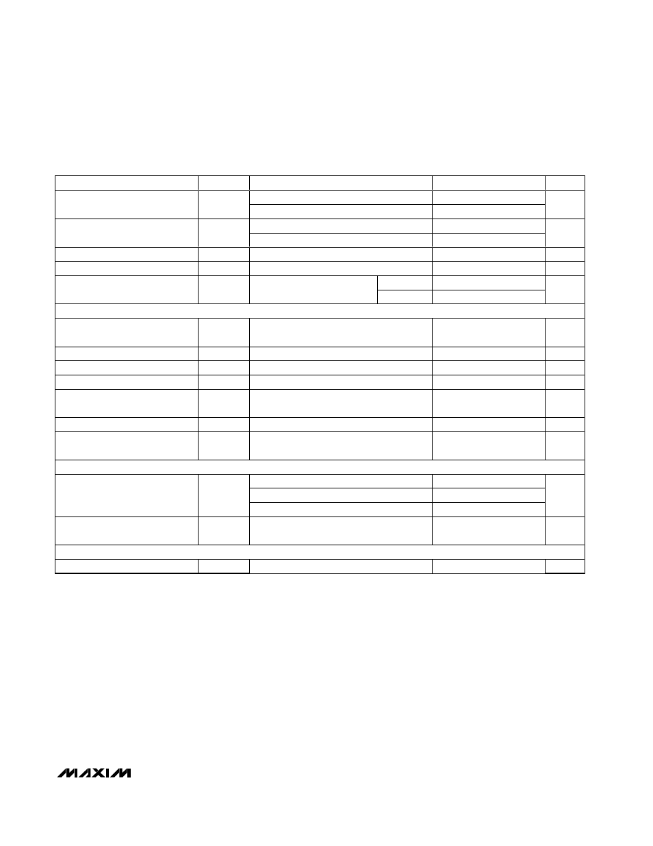
DC ELECTRICAL CHARACTERISTICS (continued)
(V
CC
= 3.3V ±10%, T
A
=T
MIN
to T
MAX
, unless otherwise noted. Typical values are at V
CC
= 3.3V and T
A
= +25°C.) (Note 1)
PARAMETER
SYMBOL
CONDITIONS
MIN
TYP
MAX
UNITS
0
≤ V
OUT
≤ 12V (Note 3)
40
250
Driver Short-Circuit Output
Current
I
OSD
-7V
≤ V
OUT
≤ V
CC
(Note 3)
-250
-40
mA
(V
CC
- 1V)
≤ V
OUT
≤ 12V (Note 3)
20
Driver Short-Circuit Foldback
Output Current
I
OSDF
-7V
≤ V
OUT
≤ 1V (Note 3)
-20
mA
Thermal-Shutdown Threshold
T
TS
175
°C
Thermal-Shutdown Hysteresis
T
TSH
15
°C
V
IN
= +12V
125
Input Current (A and B)
I
A, B
DE = GND,
V
CC
= GND or 3.6
V
IN
= -7V
-100
µA
RECEIVER
Receiver Differential Threshold
Voltage
V
TH
-7V
≤ V
CM
≤ 12V
-200
-125
-50
mV
Receiver Input Hysteresis
∆V
TH
V
A
+ V
B
= 0V
15
mV
RO Output High Voltage
V
OH
I
O
= -1mA
V
CC
- 0.6
V
RO Output Low Voltage
V
OL
I
O
= 1mA
0.4
V
Three-State Output Current at
Receiver
I
OZR
0
≤ V
O
≤ V
CC
± 1
µA
Receiver Input Resistance
R
IN
-7V
≤ V
CM
≤ 12V
96
k
Ω
Receiver Output Short-Circuit
Current
I
OSR
0V
≤ V
RO
≤ V
CC
±80
mA
SUPPLY CURRENT
No load, RE = 0, DE = V
CC
0.8
1.5
No load, RE = V
CC
, DE = V
CC
0.8
1.5
Supply Current
I
CC
No load, RE = 0, DE = 0
0.8
1.5
mA
Supply Current in Shutdown
Mode
I
SHDN
RE = V
CC
, DE = GND
0.05
10
µA
ESD PROTECTION
ESD Protection for Y, Z, A, and B
Human Body Model
±15
kV
Note 1: All currents into the device are positive. All currents out of the device are negative. All voltages are referred to device
ground, unless otherwise noted.
Note 2:
∆V
OD
and
∆V
OC
are the changes in V
OD
and V
OC
, respectively, when the DI input changes state.
Note 3: The short-circuit output current applies to peak current just prior to foldback current limiting. The short-circuit foldback out-
put current applies during current limiting to allow a recovery from bus contention.