Pin description (continued), Function tables – Rainbow Electronics MAX3079E User Manual
Page 13
MAX3070E–MAX3079E
+3.3V, ±15kV ESD-Protected, Fail-Safe,
Hot-Swap, RS-485/RS-422 Transceivers
______________________________________________________________________________________
13
MAX3070E/MAX3073E/MAX3076E
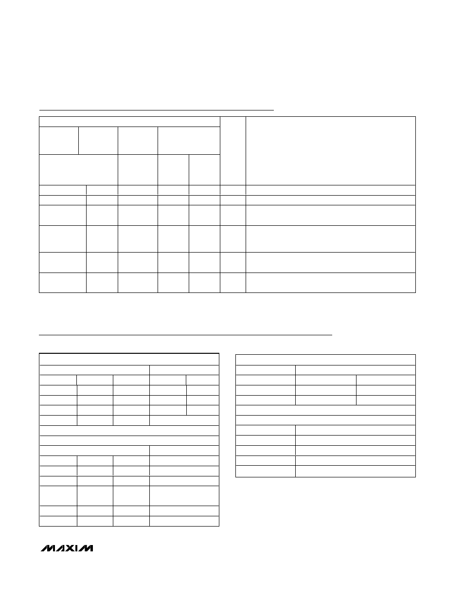
Pin Description (continued)
PIN
MAX3070E
MAX3073E
MAX3076E
MAX3071E
MAX3074E
MAX3077E
MAX3072E
MAX3075E
MAX3078E
MAX3079E
FULL-DUPLEX
DEVICES
HALF-
DUPLEX
DEVICES
FULL-
DUPLEX
MODE
HALF-
DUPLEX
MODE
NAME
FUNCTION
12
8
—
12
—
A
Noninverting Receiver Input
—
—
—
—
12
A
Receiver Input Resistors*
—
—
6
—
—
A
Noninverting Receiver Input and Noninverting Driver
Output
—
—
—
13
13
RXP
Receiver Phase. Connect RXP to GND or leave
unconnected for normal transmitter phase/polarity.
Connect to V
CC
to invert receiver phase/polarity.
14
1
8
14
14
V
CC
Positive Supply V
CC
= 3.3V ±10%. Bypass V
CC
to GND
with a 0.1µF capacitor.
1, 8, 13
—
—
—
—
N.C.
No Connect. Not internally connected. Can be connected
to GND.
*MAX3079E only. In half-duplex mode, the driver outputs serve as receiver inputs. The full-duplex receiver inputs (A and B) still have a
1/8-unit load, but are not connected to the receiver.
TRANSMITTING
INPUTS
OUTPUTS
RE
DE
DI
Z
Y
X
1
1
0
1
X
1
0
1
0
0
0
X
High-Z
High-Z
1
0
X
Shutdown
RECEIVING
INPUTS
OUTPUT
RE
DE
A, B
RO
0
X
≥ -50mV
1
0
X
≤ -200mV
0
0
X
Open/
shorted
1
1
1
X
High-Z
1
0
X
Shutdown
MAX3071E/MAX3074E/MAX30767E
TRANSMITTING
INPUT
OUTPUTS
DI
Z
Y
1
0
1
0
1
0
RECEIVING
INPUTS
OUTPUT
A, B
RO
≥ -50mV
1
≤ -200mV
0
Open/shorted
1
Function Tables