Applications information, Table 1. crystal selection parameters, Max3622 – Rainbow Electronics MAX3622 User Manual
Page 6
Applications Information
Power-Supply Filtering
The MAX3622 is a mixed analog/digital IC. The PLL
contains analog circuitry susceptible to random noise.
In addition to excellent on-chip power-supply noise
rejection, the MAX3622 provides a separate power-
supply pin, V
CCA
, for the VCO circuitry. Figure 2 illus-
trates the recommended power-supply filter network for
V
CCA
. The purpose of this design technique is to
ensure clean input power supply to the VCO circuitry
and to improve the overall immunity to power-supply
noise. This network requires that the power supply is
+3.3V ±5%. Decoupling capacitors should be used on
all other supply pins for best performance.
Crystal Selection
The crystal oscillator is designed to drive a fundamen-
tal mode, AT-cut crystal resonator. See Table 1 for rec-
ommended crystal specifications. See Figure 4 for
external capacitor connection.
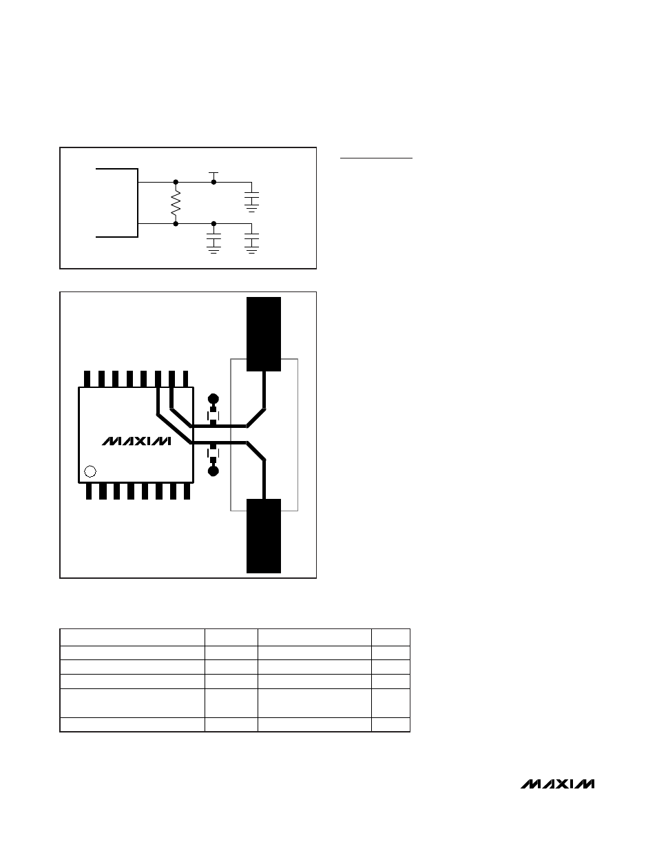
Crystal Input Layout and Frequency
Stability
The crystal, trace, and two external capacitors should
be placed on the board as close as possible to the
MAX3622’s X_IN and X_OUT pins to reduce crosstalk
of active signals into the oscillator.
The layout shown in Figure 3 gives approximately 3pF
of trace plus footprint capacitance per side of the crys-
tal (Y1). The dielectric material is FR-4 and dielectric
thickness of the reference board is 15 mils. Using a
25MHz crystal and the capacitor values of C10 = 27pF
and C9 = 33pF, the measured output frequency accu-
racy is -10ppm at +25°C ambient temperature.
Table 1. Crystal Selection Parameters
PARAMETER
SYMBOL
MIN
TYP
MAX
UNITS
Crystal Oscillation Frequency
f
OSC
25 MHz
Shunt Capacitance
C
O
2.0
7.0
pF
Load Capacitance
C
L
18 pF
Equivalent Series Resistance
(ESR)
R
S
50
Maximum Crystal Drive Level
300
μW
MAX3622
Low-Jitter, Precision Clock Generator
with Two Outputs
6
_______________________________________________________________________________________
V
CC
V
CCA
10.5
Ω
+3.3V
±5%
0.01
μF
10
μF
0.01
μF
Figure 2. Analog Supply Filtering
C 9
C 10
MAX3622
Y1
25MHz
CRYSTAL
Figure 3. Crystal Layout